We are going to have to spend time getting a development environment set up, but it is still worth seeing how easy it is to control the Edison's GPIO pins. The key to it all is the mraa library, which allows you to access the GPIO no matter which of the breakout boards you are using.
In fact mraa works on a range of other devices including the Galileo and the Raspberry Pi, so it is worth finding out about. It is a C/C++ library but it can also be used from Python or JavaScript.
To get us started, to check that everything is working, and just for a general confidence boost, we can work interactively in Python and flash an LED manually.
I say "flash an LED", but there is only a real LED to flash on the Arduino breakout board. On the mini breakout board all we can do, without adding some components, is check the voltage level on one of the outputs.
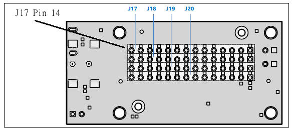
First, we have to say something about how to determine which pin number corresponds to which physical pin. Mraa uses a standard set of pin numbers which are mapped to appropriate pins on different devices - there is a lot more to say about this, but all you need to know at the moment is that mraa pin number 13 is mapped to on the Arduino breakout board to Arduino pin 13, which has an LED connected, and to pin J17-14 on the mini breakout board.
You don't need to find the pin on the Arduino breakout board because if everything works you will see the LED go on and off.
Finding the pin on the mini breakout board is easy because the pin rows are labeled and pin J17-14 is the far left pin on the top row looking at the bottom of the board:
The simplest way to make sure that the pin state changes is to use a multimeter - if you don't have one get one at once, they are cheap and essential. You can make a ground connection using the through-plated mounting holes. Remember the logic levels are 0 and 1.8V and you will see zero when the pin is set to zero and 1.8 when it is set to 1. Also be careful not to short other pads or tracks on the PCB with the multimeter probes.
Programming the Edison
Now to the software. Open a serial connection and log in if you need to. To get the Python interpreter running simply type
python
you should see a three-arrow >>> prompt appear. You can now type in any Python commands and they will be obeyed at once.
To load the mraa library use:
import mraa
if you see any error messages then the chances are that your mraa library isn't up-todate -see above.
Next we need to create a pin object:
x = mraa.Gpio(13)
and set it to be an output
x.dir(mraa.DIR_OUT)
Now we can switch the pin to high:
x.write(1)
If you are using the Arduino breakout board you should see the LED connected to pin 13 come on.
If you are using the mini breakout board you should measure 1.8V on pin J17-14.
To set the pin low use:
x.write(0)
and the LED should go off and the voltage on pin J17-14 should drop to 0V.
That's all there is to it.
You now have a working connected Edison and you can program its GPIO pins.
Of course, there is a lot more to find out and master.
Summary
The Edison breakout boards have two USB connectors - one supplies power and other services and the other is a serial port allowing you to connect to the OS.
No matter which breakout board you are using connect both USB sockets to your host machine using suitable cables.
Even without additional drivers all host machines should recognise the shared flash drive in the Edison as a hard disk with the device name Edison.
You can connect to the Edison using a serial console of your choice. Linux and OS X should have a suitable console and drivers for the USB port already installed.
If you are using Windows you need to download a USB Serial driver and a suitable serial console - Putty is probably the one to use.
Once you have made a serial connection you can log on to Yocto Linux using the user name "root" with no password.
It is important that you upgrade the OS to the latest version. Simply download the OS image and copy it to the shared drive. Then restart the Edison using reboot ota. The Edison will restart twice before the update is complete.
Use configure_edison --setup to connect to WiFi.
It is important to update the mraa library. Without the latest version things tend not to work.
With the upgraded mraa library you can now use C/C++, Python or JavaScript to control the Edison's GPIO.
You are now ready to start building programs.
More Information
The starting point for finding out about all Intel's Internet of Things resources, including Edison, is the Intel IoT Developer Zone.
Exploring Edison
Now On Sale!
You can now buy a print edition of Exploring Intel Edison.
Meet Edison In this chapter we consider the Edison's pros and cons and get an overview of its structure and the ways in which you can make use of it. If you have ever wondered if you need an Edison or an Arduino or even a Raspberry Pi then this is the place to start.
First Contact When you are prototyping with the Edison you are going to need to use one of the two main breakout boards - the Arduino or the mini. This chapter explains how to set up the Edison for both configurations.
In C You can program the Edison in Python, JavaScript or C/C+ but there are big advantages in choosing C. It is fast, almost as easy as the other languages and gives you direct access to everything. It is worth the effort and in this chapter we show you how to set up the IDE and get coding.
Mraa GPIO Using the mraa library is the direct way to work with the GPIO lines and you have to master it. Output is easy but you do need to be aware of how long everything takes. Input is also easy but using it can be more difficult. You can use polling or the Edison interrupt system which might not work exactly as you would expect.
Fast Memory Mapped I/O There is a faster way to work with GPIO lines - memory mapped I/O. Using this it is possible to generate pulses as short at 0.25 microsecond and read pulse widths of 5 microseconds. However getting things right can be tricky. We look at how to generate fast accurate pulses of a given width and how to measure pulse widths.
Near Realtime Linux You need to be aware how running your programs under a non-realtime operating system like Yocto Linux effects timings and how accurately you can create pulse trains and react to the outside world. In this chapter we look the realtime facilities in every version of Linux.
Sophisticated GPIO - Pulse Width Modulation Using the PWM mode of the GPIO lines is often the best way of solving control problems. PWM means you can dim an LED or position a servo and all using mraa.
Sophisticated GPIO - I2C I2C is a simple communications bus that allows you to connect any of a very large range of sensors.
I2C - Measuring Temperature After looking at the theory of using I2C here is a complete case study using the SparkFun HTU21D hardware and software.
Life At 1.8V How to convert a 1.8V input or output to work with 5V or 3.3V including how to deal with bidirectional pull-up buses.
Using the DHT11/22 Temperature Humidity Sensor at 1.8V In this chapter we make use of all of the ideas introduced in earlier chapters to create a raw interface with the low cost DHT11/22 temperature and humidity sensor. It is an exercise in interfacing two logic families and implementing a protocol directly in C.
The DS18B20 1-Wire Temperature The Edison doesn't have built in support for the Maxim 1-Wire bus and this means you can't use the very popular DS18B20 temperature sensor. However with a little careful planning you can and you can do it from user rather than kernel space.
Using the SPI Bus The SPI bus can be something of a problem because it doesn't have a well defined standard that every device conforms to. Even so, if you only want to work with one specific device it is usually easy to find a configuration that works - as long as you understand what the possibilities are.
SPI in Practice The MCP3008 AtoD The SPI bus can be difficult to make work at first, but once you know what to look for about how the slave claims to work it gets easier. To demonstrate how its done let's add eight channels of 12-bit AtoD using the MCP3008.
Beyond mraa - Controlling the features mraa doesn't. There is a Linux-based approach to working with GPIO lines and serial buses that is worth knowing about because it provides an alternative to using the mraa library. Sometimes you need this because you are working in a language for which mraa isn't available. It also lets you access features that mraa doesn't make available.