| Exploring Edison - SPI AtoD with the SPI Bus |
| Written by Harry Fairhead | |||||
| Monday, 20 June 2016 | |||||
Page 2 of 4
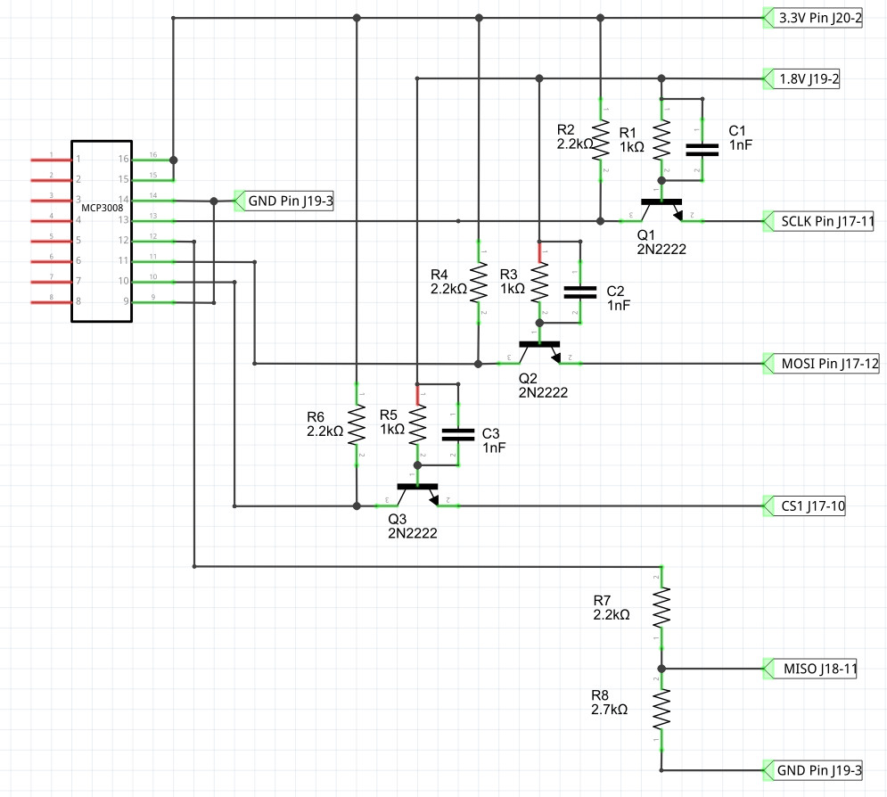
Connecting MCP3008 To The EdisonThe lower voltage operating point isn't quite low enough to allow it to work with the 1.8V Edison GPIO lines. There are 1.8V AtoD converters but they are more expensive and only available in surface mount packages. You can use an IC voltage translator and, given that there are four lines to convert, this may well be a good choice. However, the four lines are unidirectional - three output and one input to the Edison - and so simple transistor and resistor voltage translators suffice. One small problem is that a single-transistor common-emitter buffer inverts the signal. We could cope with this in software, but the SPI bus isn't easy to use in an inverted mode. However, if we used the user space driver given at the end of the previous chapter, then a simple inverting buffer could be used and corrected for in the software. To use the mraa SPI functions we need a non-inverting level translator and this is most simply achieved using the common base buffer introduced in the previous chapter and a simple resistor voltage divider. The connection to the Edison's SPI bus is simple and can be seen in the diagram below.
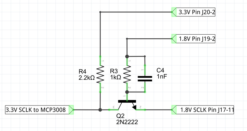
If you want to understand the way the level converter works take a look a just one of the transistor circuits:
When the SCLK is low the transistor is on because the voltage difference between the base and emitter is 1.8V. Hence the output SCLK line is pulled low via the 1K resistor. In this state the current in the Edison's GPIO line is roughly base current plus collector current: base current = (1.8-0.6)V/1K=1.2mA collector current 3.2V/2.2K=1.45mA or 2.65mA, which is below the 3mA the Edison can supply. You can increase the size of R4 but this reduces the high frequency performance. When the SCKL goes high the voltage applied to the base is below the emitter voltage and the transistor is cut off. This allows R4 to pull the output high. In this mode state the current supplied by the Edison is negligible. The only remaining component to explain is C4. This is a traditional "speed up" capacitor. Bipolar transistors take longer to switch off than switch on because of charge stored in the base region. The speed up capacitor provides charge to neutralize the base charge and so allows the transistor to switch off faster. A better alternative is to use a Schottky diode to stop the transistor going into deep saturation, but at the sort of speeds the Edison works at the capacitor is good enough. The only additional component that is recommended is a 1uF capacitor connected between pins 15 and 16 to ground, mounted as close to the chip as possible. As discussed in the previous section, you might want a separate voltage reference for pin 15 rather than just using the 3.3V supply. Basic ConfigurationNow we come to the configuration of the SPI bus. We have some rough figures for the SPI clock speed - 10kHz to a little more than 1.35MHz. So an initial clock frequency giving a frequency of 1MHz seems a reasonable starting point. This also means that the clock is in the region where the DMA transfer works correctly. However as we are only transferring three bytes the DMA works at lower frequencies. From the data sheet the CS has to be active low and the most significant bit first is the default for both the master and the slave. The only puzzle is what mode to use? This is listed in the data sheet if you look really carefully. It can be mode 0,0 with clock active high or mode 1,1 with clock active low. For simplicity we can use mode 0,0 which is mode0 in the bcm2835 library. We now have enough information to initialize for the slave:
The ProtocolNow we have the SPI initialized and ready to transfer data but what data do we transfer? The SPI bus doesn't have any standard commands or addressing structure. Each device responds to data sent in different ways and sends data back in different ways. You simply have to read the data sheet to find out what the commands and responses are. Reading the data sheet might be initially confusing because it says that what you have to do is send five bits to the slave - a start bit, a bit that selects its operating mode single or differential and a three bit channel number. The operating mode is 1 for single ended and 0 for differential. So to read channel 3 i.e. 011, in single ended mode you would send the slave:
where xxx means don't care. The response from the slave is that it holds its output in a high impedance state until the sixth clock pulse it then sends a zero bit on the seventh followed by bit 9 of the data on clock eight. That is the slave sends back:
where x means indeterminate and b9 is zero or one depending on the data. The remaining nine bits are sent back in response to the next nine clock pulses. This means you have to transfer three bytes to get all ten bits of data. This all makes reading the data in eight-bit chunks confusing. The data sheet suggests a different way of doing the job that delivers the data more neatly packed into three bytes. What it suggests is to send a single byte
The slave transfers random data at the same time which is ignored. The final 1 is treated as the start bit. If you now transfer a second byte with most significant bit indicating single or differential mode, then a three-bit channel address and the remaining bits set to zero, the slave will respond with the null and the top two bits of the conversion. Now all you have to do to get the final eight bits of data is to read a third byte:
You can do it the first way that the data sheet describes, but this way you get two neat bytes containing the data with all the low-order bits in their correct positions. Using this information we can now write some instructions that read a given channel. For example, to read channel zero we first send a byte set to 0x01 as the start bit and ignore the byte the slave transfers. Next we send 0x80 to select single-ended and channel zero and keep the byte the slave sends back as the high-order two bits. Finally we send a zero byte so that we get the low-order bits from the slave:
Notice you cannot send the three bytes one at a time using transfer because that results in the CS line being deactivated between the transfer of each byte. To get the data out of readBuf we need to do some bit manipulation:
The first part of the expression extracts the low three bits from the first byte the slave sent and as these are the most significant bits they are shifted up eight places. The rest of the bits are then ORed with them to give the full 10-bit result. To convert to volts we use:
assuming that VREF is 3.3V. In a real application you would also need to convert the voltage to some other quantity such as temperature or light level. Some Packaged FunctionsThis all works but it would be good to have a function that read the AtoD on a specified channel:
Notice that this only works if the SPI bus has been initilized and set up correctly. An initalization function is something like:
And these could be used something like:
|
|||||
| Last Updated ( Monday, 20 June 2016 ) |