|
Page 1 of 5 The CM5 supports PWM and you can direct access to its hardware using the GPIO5 library. This is an extract from the newly-published Raspberry Pi Compute Module 5 IoT In C
Raspberry Pi Compute Module 5
IoT In C
Using Linux Drivers and Gpio5
By Harry Fairhead
Buy from Amazon.
Contents
- The CM5 For The IoT
- Setting Up the CM5
- C and Visual Studio Code
- Drivers: A First Program
- The GPIO Character Drive
- GPIO Using I/O Control
- GPIO Events
- GPIO Hardware With Gpio5
- Some Electronics
- The Device Tree
- Pulse Width Modulation
Extract: PWM Using GPIO5
- SPI Devices
- I2C Driver and Gpio5
- Sensor Drivers – Linux IIO & hwmon
- 1-Wire Bus
- The PIO
Extract: Getting Started With PIO ***NEW!!!
- Going Further With Drivers
- Almost Real-Time Linux
- Appendix I Gpio5
In Chapter but not in this extract
- Pulse Width Modulation
- Some Basic Pi PWM Facts
- Software PWM
- The PWM Driver
- Simple PWM Functions
Using PWM Hardware – Extending Gpio5
The Linux drivers are easy enough to use, but they don’t allow you to use all four channels, to set the clock frequency or to use any of the additional modes that the hardware supports. An attractive alternative is to access the PWM hardware directly via an extension to the Gpio5 library which takes it beyond just controlling the GPIO lines directly.
The CM5 has four PWM channels which correspond to GPIO lines:
      function 0  function 3
PWM 0  GPIO12
PWM 1  GPIO13
PWM 2  GPIO14      GPIO18
PWM 3  GPIO15      GPIO19
It is easier to use GPIO12 to GPIO15 as they can be enabled using the same function code.
All GPIO lines set to PWM expect the PAD to be correctly configured by additional code.
PWM Modes
The CM5’s PWM hardware is more sophisticated than other hardware you might have encountered before. The first big difference is that it can work in a number of modes that generate different types of signal.
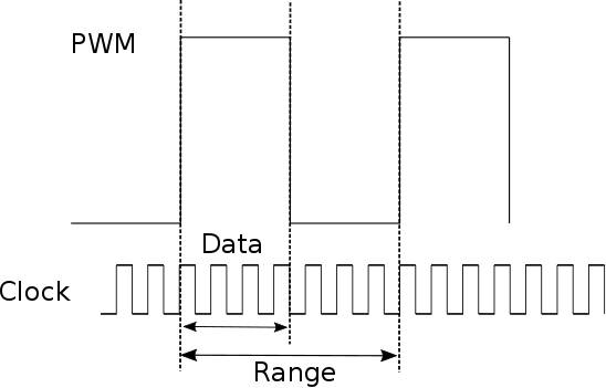
The basic PWM signal is generated using a 32-bit counter that rolls over at Range, the range boundary, or at zero depending on whether it is counting up or down. The value of Duty determines when the signal is high.
trailing-edge mode the counter starts at zero and counts up to range before rolling over. The output is a one when the count is less than the value of Duty and a zero when it is greater.
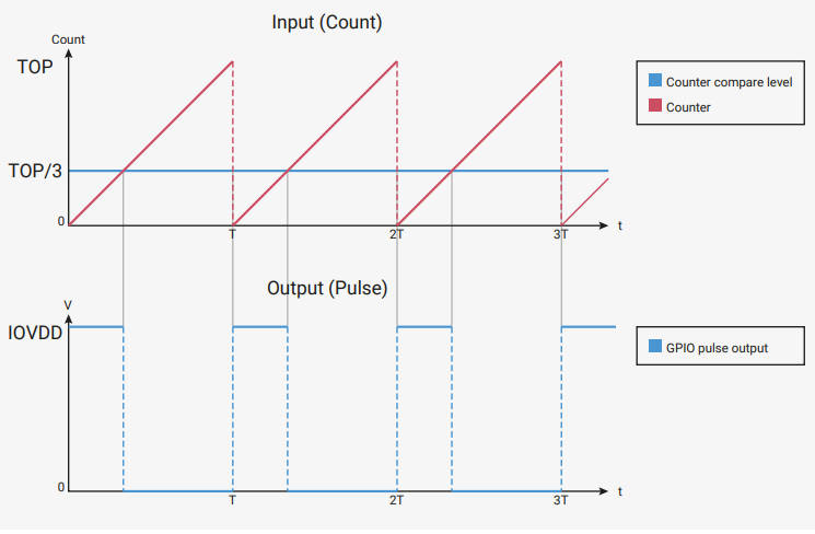
In leading-edge mode the count starts at Range and counts down to zero before rolling over. The output is a one when count is less than Duty. This produces a signal 180 degrees out of phase with trailing-edge mode.

In double-edge mode the count starts at Range and counts down to zero and then starts to count up to Range before repeating. The output is high when the count is less than Duty. This produces a “phase-corrected” signal with the pulse at the center of the time slot:
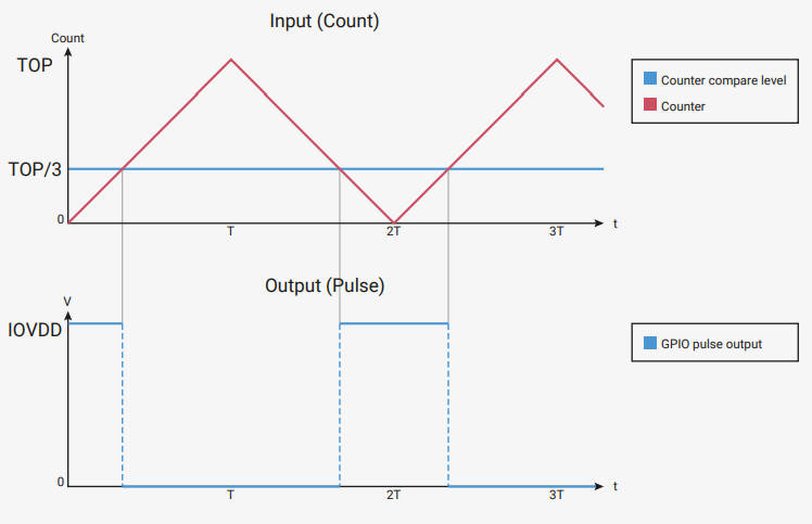
|