| ESP32 In MicroPython: PWM And The Duty Cycle |
| Written by Harry Fairhead & Mike James | |||
| Monday, 21 August 2023 | |||
Page 1 of 2 The PWM hardware available on the ESP32 is a little more complicated than you might expect and some things might be better achieved using the RMT. This extract is from Programming the ESP32 in MicroPython, part of the I Programmer Library and it shows you how to use the PWM hardware. Programming the ESP32in MicroPythonBy Harry Fairhead & Mike James
Buy from Amazon. ContentsPreface
<ASIN:187196282X> In chapter but not in this extract
ESP32 PWMThe ESP32 has two PWM hardware implementations. One is intended for use in motor control and has extra features such as a dead zone and autobraking. This isn’t supported by MicroPython and if you want to make use of it then you have to move to C. The second, LEDC, is specifically designed to drive LEDs with facilities such as auto-dimming plus more exotic features. While MicroPython does support the basic LEDC operations it doesn’t provide access to all its additional features. A PWM generator can be assigned to any GPIO pin. The number of PWM generators an ESP32 has depends on its exact model. They come in two groups – fast and slow. The fast type has the autodimming features and is able to smoothly change frequency and duty cycle. The slow type lacks these features and it is up to software to change its frequency and duty cycle. Each group also has a set number of timers which determine how many different frequencies can be generated and a given number of channels. The most common development board using an EP32 has two groups, one fast and one slow, of PWM with eight channels in each group. The ESP32-S2 only has one fast group, but is otherwise identical. The ESP32-C3, which is RISC based, is the same as the ESP32-S2, but with only six channels. All ESP32 devices have four timers in each group, meaning you can set four different frequencies. The distinction between the two groups is irrelevant from the point of view of MicroPython as it doesn’t make use of the extra features in the fast group. What this means is that, from the point of view of MicroPython, an ESP32 has 16 PWM channels which can work at eight different frequencies. All of the channels can work at different duty cycles. You don’t have to know about how the PWM hardware works, but it helps with understanding some of the restrictions. To create a PWM object you have to pass its constructor a Pin object. For example: pwm1 = PWM(Pin(4)) creates a PWM object associated with GPIO4. You can set the frequency using: pwm1.freq(500) which sets the frequency in Hz. The PWM hardware isn’t enabled at this point. To start it generating a signal you have to set the duty cycle. This is done using: pwm1.duty_u16(duty) where duty is a value in the range 0 to 65,535 corresponding to 0 to 100%. There is also: pwm1.duty_ns(ns) which sets the time the line is high in nanoseconds. This isn’t as useful for general use and if you specify a time that is greater than the set period you will generate an exception. Alternatively you can use the constructor to specify all of the characteristics of the PWM: machine.PWM(dest, freq=f, duty_u16=d, duty_ns=t) At the time of writing there is a bug in MicroPython 1.19 which causes the duty cycle to be set incorrectly if the frequency is set using freq(). A fix is to always use the constructor to set an initial frequency. The MicroPython implementation of PWM allocates timers to channels in an intelligent way. If you create a PWM object working at a particular frequency it first looks to see if there is a timer in the same group working at that frequency. If there is it allocates it to the PWM object. If there isn’t an existing timer working at that frequency then a free one is allocated and set to work at the new frequency. If there are no free timers left and none are running at the frequency required then an exception is thrown. What this means is that you can allocate frequencies without worrying until you have used up all of the timers and then you have to set frequencies you have already used. This means that for an ESP32 you can set up to eight different frequencies for the 16 different channels. You can easily create your own duty cycle methods that work in terms of percentages or whatever way you want to specify the duty cycle. For example, you can create a new class which has a duty cycle set as a percentage: class myPWM(PWM):
def __init__(self, pin: Pin):
super().__init__(pin)
def duty(self,d):
print(65535*d//1000)
super().duty_u16(65535*d//1000)
In this case the percentage is specified multiplied by 10. For example, to set a 50% duty cycle you would use: pwm1 = myPWM(Pin(4),freq=250) pwm1.duty(500) Once you have set the duty cycle the PWM generator starts to output the specified PWM signal on the pin. Notice that this works even after your program has completed. To stop the PWM signal use: pwm16.deinit()
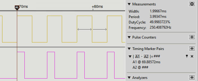
You can change the frequency or duty cycle at any time. For example: from machine import Pin, PWM pwm1 = PWM(Pin(4),freq=250) pwm2 = PWM(Pin(16),freq=250) pwm1.duty_u16(65535//2) pwm2.duty_u16(65535//4)
You can see from this trace that the pulses on each line start their duty cycle at exactly the same time. |
|||
| Last Updated ( Monday, 21 August 2023 ) |