| ESP32 In MicroPython: GPIO |
| Written by Harry Fairhead & Mike James | |||||||||||
| Monday, 18 December 2023 | |||||||||||
Page 2 of 2
Basic GPIO FunctionsThe MicroPython Pin class allows you to create an object which controls the way a single GPIO line works. The simplest form of the constructor is: Pin(id, mode = mode) where id is the number of the GPIO line you want to use and mode is Pin.IN or Pin.OUT. There are other possibilities and these are discussed later. Notice that id is the GPIO number and not the hardware pin number. For example, 5 means GPIO5 and not “connector pin 5” but connector J3 pin 10. There is also an init method which can be used to change the configuration of the pin. For example, pin.init(mode = Pin.IN) might be used to change a pin from output to input. A number of methods are provided to work with the state of a Pin object:
There are a number of other methods and properties, but these are the most basic. You can discover the current state of a GPIO line using state = pin.value() and you can set the initial state of a GPIO output using value = in the constructor or in the init method. BlinkyBy tradition, the first IoT program you write is Blinky which flashes an LED. A program to flash an LED uses a general I/O line and an external LED. Some development boards have an LED already connected to GPIO2. With this in mind, let’s flash an LED connected to GPIO2 which will either use the onboard LED or an external LED you have connected. Enter the program: from machine import Pin
import time
pin = Pin(2, Pin.OUT)
while True:
pin.value(1)
time.sleep(1)
pin.value(0)
time.sleep(1)
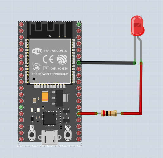
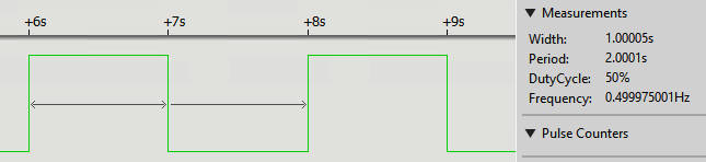
The program doesn’t use any constants in order to make what is happening clearer. It first initializes GPIO2 to be an output and sets it repeatedly high and low with a pause of one second in between. If the board you are using has an LED connected to GPIO2 you will see it flashing. If not and you want to connect an LED to see the "blinking" for real then this is easy enough, but you do need a current-limiting resistor to avoid the LED drawing more current than the GPIO line can supply and possibly damaging the chip. A 200Ω resistor is a good choice, see Chapter 5, where a better way to drive an LED is also discussed.
How you build the circuit is up to you. You can use a prototyping board or just a pair of jumper wires. The short pin and/or the flat on the side of the case marks the negative connection on the LED – the one that goes to ground.
Adding A Function ToggleThe ESP32 doesn’t support a toggle function, but it is easy to add one: def toggle(pin):
temp = pin.value()
temp = not temp
pin.value(temp)
This sets a line high it if it is low and low if it is high. This form of the function shows how it works, but in practice you would probably write it in a more compact form: def toggle(pin):
pin.value(not pin.value())
With toggle it is even easier to implement Blinky: from machine import Pin
import time
pin = Pin(2,Pin.OUT)
while True:
toggle(pin)
time.sleep(1)
Summary
Programming the ESP32in MicroPythonBy Harry Fairhead & Mike James
Buy from Amazon. ContentsPreface
<ASIN:187196282X>
Comments
or email your comment to: comments@i-programmer.info To be informed about new articles on I Programmer, sign up for our weekly newsletter, subscribe to the RSS feed and follow us on Twitter, Facebook or Linkedin. |
|||||||||||
| Last Updated ( Tuesday, 19 December 2023 ) |