| ESP32 In MicroPython: Using Hardware Registers |
| Written by Harry Fairhead & Mike James | ||||||||||||||||||||
| Monday, 19 June 2023 | ||||||||||||||||||||
Page 3 of 3
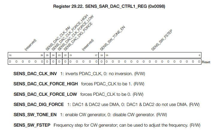
Example II – Sine Wave GeneratorMicroPython doesn’t provide access to the sine wave generator included in the DAC. It is, however, fairly easy to configure and enable it by directly working with its registers. There is only one sine wave generator for both DACs, but each one can set its own scale, offset and phase. If you look at the manual you will find the analog register summary and listed are two registers for the DAC system:
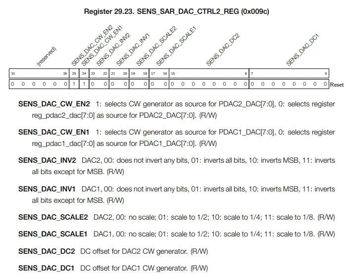
You can see that the first register has a single bit that enables the sine wave generator – bit 16, SENS_SW_TONE_EN and a 16-bit field, SENS_SW_FSTEP, that sets the frequency. Looking back at the description of the sine wave generator, we find the expression: freq = dig_clk_rtc_freq · SENS_SAR_SW_FSTEP/65536 and that the clock is 8MHz. This gives: step = int(f*65536/8000000) & 0xFFFF Looking at the details of the second register:
You can see that there are two bits, SENS_DAC_CW_EN1 and SENS_DAC_CW_EN2, which select the input source for each DAC, 1 or 2 respectively. Setting either bit to 1 connects the DAC to the sine wave generator and setting it to 0 connects the DAC to the usual register that sets the output level. The two 2-bit fields SENS_DAC_INV1 and SENS_DAC_INV2 are a mystery and don’t seem to do what they were intended to. Setting the field to 00 or 10 produces a very strange waveform. Setting the field to 01 or 11 produces a pair of sine waves that differ by 180 degrees. The two settings 00 and 10 were intended to produce 90° and 270° phase shifts, but these don’t seem to work. The two 2-bit fields SENS_DAC_SCALE1 and SENS_DAC_SCALE2 scale the output by 00 = no scaling, 01 = 1/2, 10 = 1/4 and 11 = 1/8. Finally the two 8-bit fields SENS_DAC_DC1 and SENS_DAC_DC2 set the offset. We need a set of functions that set the appropriate bits in the control registers. The easiest three to set are phase, scale and offset. To set phase to p, a two-bit value, we need to change bits 20 and 21 for DAC 1 and 22 and 23 for DAC 2. This can be done using a single function: def setPhase(chan,p):
_reg_set(0x3FF4889c, p << (20 + 2 * (chan – 1)),
0x03 << (20 + 2 * (chan - 1)))
The mask is computed using the chan parameter which is 1 or 2. If it is 1 then the mask works out to: 0x03 << 20 which sets the mask to only allow modification of bits 20 and 21. If chan is 2 then mask works out to: 0x03 << 22 which allows modification of bits 22 and 23. The value is worked out in the same way so as to store the two-bit value in the same bits as the mask. Once you have seen how to set a bit field with a specified size and location it is easy to generalize and setScale and setOff are: def setScale(chan,s):
_reg_set(0x3FF4889c, s << (16 + 2 * (chan - 1)),
0x03 << (16 + 2 * (chan - 1)))
def setOff(chan,off):
_reg_set(0x3FF4889c, off << (8 * (chan - 1)),
A setFreq function is only slightly more difficult in that we have to calculate the step value from the specified frequency: def setFreq(chan,f):
if chan<1 or chan>2:
return
step = int(f*65536/8000000) & 0xFFFF
_reg_set(0x3FF48898, step, 0x000FF)
Finally we need to enable the sine generator. It is assumed that the DAC is already set up correctly using MicroPython and all we have to do is set the additional bits to turn the sine wave generator on and connect it to the appropriate DAC,
A function to do this is now relatively easy: def enableSin(chan,f):
if chan<1 or chan>2:
return
setFreq(chan, f)
setPhase(chan,0x2)
#enable tone
_reg_set(0x3FF48898, 0x10000, 0x10000)
#select channel
if chan==1:
_reg_set(0x3FF4889c, 1<<24,0x1<<24)
else:
_reg_set(0x3FF4889c, 1<<25, 0x1 <<25)
Putting all this together gives us a complete set of functions to control the sine wave generator: from machine import Pin, DAC, mem32
from time import sleep
def _reg_get(adr):
return mem32[adr]
def _reg_set( adr,value, mask):
mem32[adr] = mem32[adr] & ~mask | value & mask
def enableSin(chan,f):
if chan<1 or chan>2:
return
setFreq(chan, f)
setPhase(chan,0x2)
#enable tone
_reg_set(0x3FF48898, 0x10000, 0x10000)
#select channel
if chan==1:
_reg_set(0x3FF4889c, 1<<24,0x1<<24)
else:
_reg_set(0x3FF4889c, 1<<25, 0x1 <<25)
def setFreq(chan,f):
    if chan<1 or chan>2:
        return
    step = int(f*65536/8000000) & 0xFFFF
    _reg_set(0x3FF48898, step, 0x000FF)
def setPhase(chan,p):
_reg_set(0x3FF4889c, p << (20 + 2 * (chan – 1)),
The scale factor s is restricted to two bits and the scaling is given by 2s. The offset is seven bits and if the scale factor isn’t used clipping will occur. Phase is two bits and only 2 and 3 can be used, corresponding to phase shifts of 0 degrees and 180 degrees. Notice that the phase shift also shifts the offset, which is generally undesirable. Once we have these functions we can make use of the sine wave generator: dac1 = DAC(Pin(26))
enableSin(2,30000)
setScale(2,0x0)
setOff(2,0x0)
while(True):
sleep(0.001)
setPhase(2,0x3)
sleep(.001)
setPhase(2, 0x2)
The standard MicroPython DAC object is used to enable the DAC hardware. After this we can use the functions to modify the control registers. The example sets a frequency of 30KHz and then modulates its phase between 0 and 180 degrees. In chapter but not in this extract
Summary
Programming the ESP32in MicroPythonBy Harry Fairhead & Mike James
Buy from Amazon. ContentsPreface
<ASIN:187196282X>
Comments
or email your comment to: comments@i-programmer.info To be informed about new articles on I Programmer, sign up for our weekly newsletter, subscribe to the RSS feed and follow us on Twitter, Facebook or Linkedin. |
||||||||||||||||||||
| Last Updated ( Tuesday, 20 June 2023 ) | ||||||||||||||||||||