| ESP32 In MicroPython: I2C, HTU21D and Slow Reading |
| Written by Harry Fairhead & Mike James | ||||||||||||||||||||||||||||||||||||||
| Monday, 10 July 2023 | ||||||||||||||||||||||||||||||||||||||
Page 2 of 4
A First ProgramAfter wiring up any I2C device, the first question that needs to be answered is, does it work? Unfortunately for most complex devices finding out if it works is a multi-step process. Our first program aims to read some data back from the HTU21D, any data will do. If you look at the datasheet you will find that the device address is 0x40 and that it supports the following commands/registers:
The easiest of these to get started with is the Read user register command. The user register gives the current setup of the device and can be used to set the resolution of the measurement. Notice that the codes that you send to the device can be considered as addresses or commands. In this case you can think of sending 0xE7 as a command to read the register or the read address of the register, it makes no difference. In most cases, the term “command” is used when sending the code makes the device do something, and the term “address” is used when it simply makes the device read or write specific data. To read the user register we have to write a byte containing 0xE7 and then read the byte the device sends back. This involves sending an address frame, a data frame, and then another address frame and reading a data frame. The device seems to be happy if you send a stop bit between each transaction or just a new start bit. A program to read the user register is fairly easy to put together. The address of the device is 0x40, so its write address is 0x80 and its read address is 0x81. Recall that bus addresses are shifted one bit to the left and the base address is the write address and the read address is base address+1. As the I2C functions adjust the address as needed, we simply use 0x40 as the device's address, but it does affect what you see if you sample the data being exchanged: from machine import Pin,I2C
i2c0 = I2C(0,scl=Pin(18),sda=Pin(19),freq=100000)
buf = bytearray([0xE7])
i2c0.writeto( 0x40, buf, True)
read= i2c0.readfrom(0x40, 1, True)
print("User Register =",read)
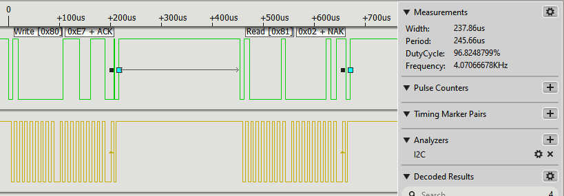
This sends the address frame 0x80 and then the data byte 0xE7 to select the user register. Next it sends an address frame 0x81 to read the data. If you run the program you will see: User Register = 2 This is the default value of the register and it corresponds to a resolution of 12 bits and 14 bits for the humidity and temperature respectively and a supply voltage greater than 2.25V. You can use the special read from a register method to do the same job: read = i2c0.readfrom_mem(0x40,0xE7,1) This does exactly the same as the previous code – it writes 0xE7 to device 0x40 and then reads one byte. The I2C Protocol In ActionIf you have a logic analyzer that can interpret the I2C protocol connected, what you will see is:
You can see that the write_byte function sends an address packet set to the device's 7-bit address 0x40 as the high-order bits with the low-order bit set to zero to indicate a write, i.e 0x80. After this you get a data packet sent containing 0xE7, the address of the register. After 237 microseconds it sends the address frame again, only this time with the low-order bit set to one to indicate a read. The gap between the operations is rather long and it slows things down. It then receives back a single byte of data from the device, 0x02. Also notice the start and stop bits at the end of each byte. The big gap between the write and the read is due to the time it takes MicroPython to process the method call. It is a limiting factor on how fast I2C can work. This all demonstrates that the external device is working properly and we can move on to getting some data of interest. Reading Temperature Data – Clock StretchingNow we come to reading one of the two quantities that the device measures, temperature. If you look back at the command table you will see that there are two possible commands for reading the temperature:
What is the difference between Hold master and No Hold master? This was discussed earlier in a general context under the section Slow Read Protocols. The device cannot read the temperature instantaneously and the master can either opt to be held waiting for the data, i.e. Hold master, or released to do something else and poll for the data until it is ready, i.e No Hold master. The Hold master option works by allowing the device to stretch the clock pulse by holding the line low after the master has released it. In this mode the master will wait until the device releases the line. Not all masters support this mode, but the ESP32 does and in theory this makes it the simpler option. To read the temperature using the Hold master mode you simply send 0xE3 and then read three bytes. The simplest program that might work is: from machine import Pin,I2C
i2c0 = I2C(0,scl=Pin(18),sda=Pin(19),freq=100000)
buf = bytearray([0xE3])
i2c0.writeto( 0x40, buf, True)
read = i2c0.readfrom(0x40, 3, True)
msb = read[0]
lsb = read[1]
check = read[2]
print("msb lsb checksum =", msb, lsb, check)
If you try it out you will see: Traceback (most recent call last): File "<stdin>", line 11, in <module> OSError: [Errno 116] ETIMEDOUT The problem is that the ESP32 doesn’t wait long enough for the clock stretching to complete. You can try adding timeout=0xFFFFF to set the timeout to its maximum, but this is already the default and so it makes no difference. The reason that the clock stretch times out is that the physical units used for the timeout are very small – number of 80MHz clock pulses set by a 20-bit number. So a maximum timeout of 0xFFFFF is equivalent to about 13ms which is nowhere near the 40ms needed by the device. So the ESP32 does support clock stretching, but only if it is less than around 13ms. To see how clock stretching works, one solution is to switch to the software implementation of I2C: from machine import Pin,SoftI2C
i2c0 = SoftI2C(scl=Pin(18),sda=Pin(19),freq=100000)
buf = bytearray([0xE3])
i2c0.writeto( 0x40, buf, False)
read= i2c0.readfrom(0x40, 3, True)
msb = read[0]
lsb = read[1]
check = read[2]
print("msb lsb checksum =", msb, lsb, check)
Now it just works. The read bytearray is unpacked into three variables with more meaningful names:
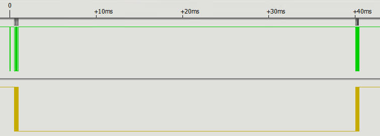
If you try this out you should find that it works and it prints something like: with temperatures in the 20°C range. You can also use the read register method to do the same job: read=i2c0.readfrom_mem(0x40, 0xE3, 3) The logic analyzer reveals what is happening. First we send the usual address frame and write the
The clock line is held low by the device for about 40ms while it gets the data ready. It is released and the three data frames are sent. This response is a long way down the logic analyzer trace (40ms+) so keep scrolling until you find it. Notice that we suppress the stop bit between the write and the read to make it a single transaction. |
||||||||||||||||||||||||||||||||||||||
| Last Updated ( Tuesday, 11 July 2023 ) |