| ESP32 In MicroPython: GPIO |
| Written by Harry Fairhead & Mike James | |||||||||||||||
| Monday, 18 December 2023 | |||||||||||||||
Page 1 of 2 GPIO is fundamental to connecting with the outside world. This extract from Programming the ESP32 in MicroPython, part of the I Programmer Library, shows you how to get started with GPIO. Programming the ESP32in MicroPythonBy Harry Fairhead & Mike James
Buy from Amazon. ContentsPreface
<ASIN:187196282X> In this chapter we take a look at the basic operations involved in using the ESP32’s General Purpose Input/Output (GPIO) lines with an emphasis on output. We’ll consider questions such as how fast can you change a GPIO line, how do you generate pulses of a given duration and how can you change multiple lines in sync with each other? ESP PinsThe first thing to make ourselves familiar with is the layout and range of GPIO pins available on a typical development board – some development boards have fewer or differently arranged pins. Most development boards are based on the ESP32-DevKitC and later boards often have additional onboard LEDs. The pins are usually described on the PCB and you can use this to confirm that the development board you are using has a particular pin configuration. All of the pins have multiple uses, most of which we will explore in later chapters, but here we concentrate on their simplest use as GPIO General Purpose Input Output lines. A GPIO line can be configured as an input or an output, but what is important even at this early stage is that you know that the ESP32 is a 3.3V device. This means that a GPIO line works with two voltages, 0V and 3.3V. If you try to use a GPIO line at a higher voltage then you risk damaging the ESP32. You can power the ESP32 via the USB port, which is the easiest way while you are developing software. You can also supply 5V via the 5V pin and it will be regulated down to 3.3V or you can connect a 3.3Vsupply to the 3.3V pin. You can only use a single method of powering the ESP32. The ESP32 has 34 physical GPIO lines in four groups, GPIO0 to GPIO19, GPIO21 to GPIO23, GPIO25 to GPIO27 and GPIO32 to GPIO39. Pins GPIO34 to GPIO39 are input only. There are other GPIO numberings in use, for example to be compatible with the Arduino development system, but these correspond to the hardware numbers. Notice that GPIO37 and GPIO38 are not available on most development boards. The following GPIO lines are used for other purposes and should be avoided:
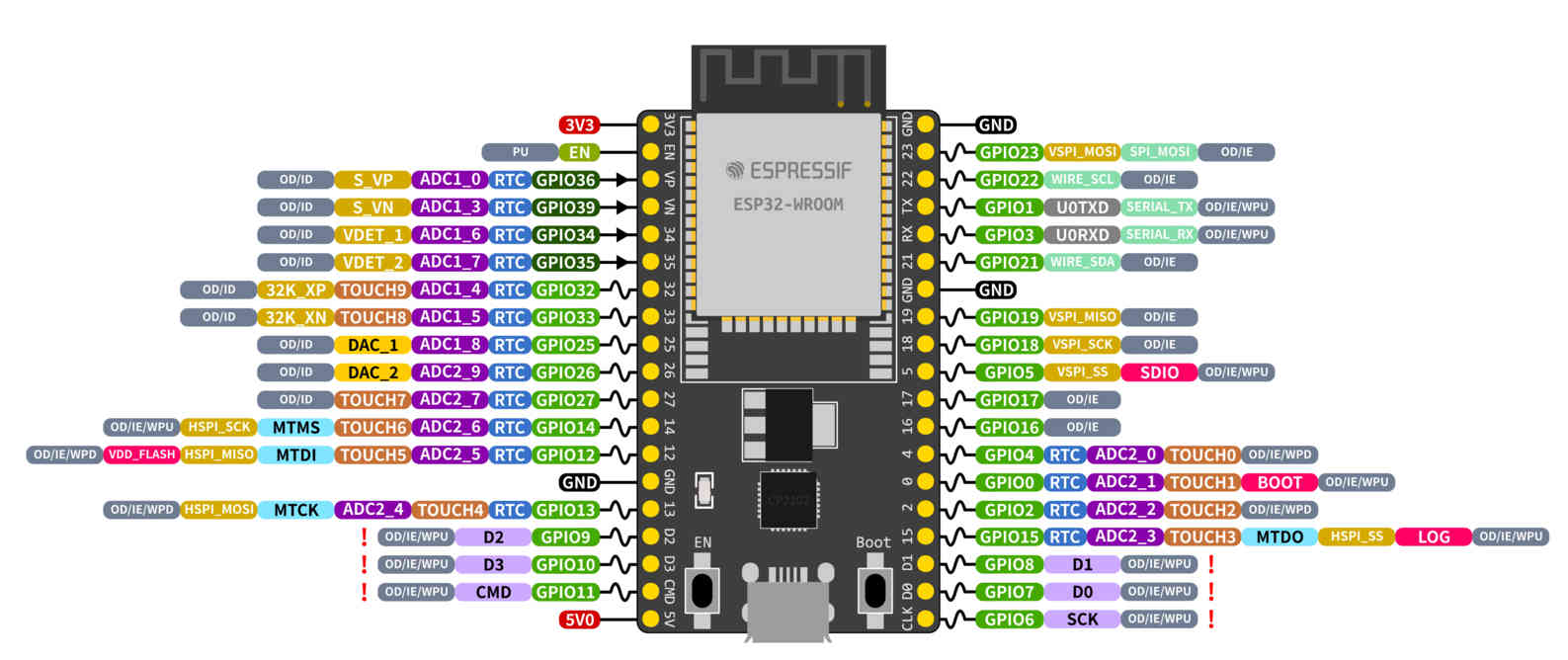
As is the case with most microprocessors, each GPIO line has multiple uses as you can see in the diagram (ESP32):
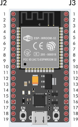
There are similar diagrams for the ESP-S2 and ESP-S3 development boards – to see the fine details of this diagram view the image on the book’s web page at www.iopress.info. You can select what mode a pin is used in and in this chapter we concentrate on using pins in the simplest GPIO mode. Even so, which pins you select for general-purpose use should take into account what other uses you might put pins to. In general you can use pins GPIO4, 5, 13 - 33 for general I/O and pins GPIO34-39 for input only. GPIO2 can also be used for general I/O if it isn’t connected to an onboard LED. Another complication is that some pins are used when the ESP32 boots to set its state. Pins GPIO0, GPIO2, GPIO12 and GPIO15 are “Strapping Pins” and if you use pull-up or pull-down resistors to set their initial state you will change the behavior of the ESP32 when it boots. Pins GPIO1, GPIO3, GPIO5, GPIO14 and GPIO15 are also used by the system at start up to send boot status data. This means that on boot these pins change state rapidly and could trigger any devices connected to them leading to difficult to find bugs. Notice that, unlike when programming directly to the hardware, MicroPython doesn’t use the idea of setting the GPIO pin into a particular mode. Instead it provides classes that make use of GPIO pins in particular ways. For example, if you were programming directly to the hardware you would first set the pins you wanted to use to the mode you wanted to use, e.g. PWM (Pulse Width Modulation) and then you would start working with PWM operations. In MicroPython you would simply create a PWM object using the pin in question and expect it to take care of setting the pin to the correct mode. Notice, however, that you are still restricted to using pins that support the mode you are using. There is no standard notation for which physical pin to connect to, but if the development board is based on the ESP32-DevKitC or similar the two connectors on either side are called J2 and J3 and the pins are numbered sequentially:
|
|||||||||||||||
| Last Updated ( Tuesday, 19 December 2023 ) |