| WPF The Easy 3D Way |
| Written by Mike James | |||||
| Wednesday, 10 June 2015 | |||||
Page 1 of 4 WPF provides a full 3D graphics experience without the need to master DirectX. It really is the easy 3D approach. 
WPF – Windows Presentation Foundation supports so much more than buttons and boxes. It is essentially a wrapper around DirectX and hence offers you a complete 3D with animation facility. We have already taken a look at the WPF form controls and the XAML markup language. In this project the focus falls on a different aspect of WPF – its 3D graphics. Classic Windows forms are rendered to a physical device by the GDI (Graphics Device Interface) and, later by the GDI+. XAML forms are rendered by the DirectX graphics engine and don’t make use of the GDI at all. Many of the WPF graphics facilities are managed wrappers and extensions of DirectX. What this means is that all drawing is essentially 3D and, with the correct graphics card, hardware accelerated. This causes some problems if you try to mix old style GDI/GDI+ graphics with the WPF graphics but is probably worth it to get the benefits of the sophisticated and fast DirectX graphics system. So download a copy of Visual Studio Community Edition if you don't have full Visual Studio and start coding. 3D fundamentals In the previous project we looked at WPF as a general purpose forms facility and worked with 2D buttons and so on, all rendered behind the scenes by the 3D DirectX graphics engine. This project starts from the other end the spectrum and looks directly at the 3D graphics facilities. Seeing WPF from the 3D end of the spectrum gives a unique perspective on the framework and will help you see how to use forms and 3D together. The first thing to be clear about is that a 3D model with its associated “view” is a prescription for creating a 2D display on the screen. In this sense the display part of WPF is the same for 3D as for forms i.e.a 2D bitmap. The Viewport3D object is the system component that does the conversion by taking a 3D model and rendering it as a 2D visual element that can be placed in a container element like a Grid or a Canvas. In this sense the Viewport3D is just like a button or a textbox that can be placed on a form. This is how 3D and forms fit together. Immediate And Retained ModeIf you are familiar with DirectX you will recognise many of its 3D objects in WPF. However, there is one feature that you would need to go back to before DirectX 8 to have encountered. WPF uses “retained” mode graphics, which is ideal for forms and buttons. If you draw a button on a form and another form temporarily covers it up then the system takes care of the re-draw when the button becomes visible again. That is, all of the graphics that you place on a form are retained until you explicitly dispose of them. This may be ideal for forms but it’s not the way DirectX 9 and later work. For games it proves to be faster and more efficient to simply provide the 3D model for each action frame and it’s up to the application not the system to re-draw everything each time the image is rendered to 2D. That is each time a frame is displayed the software has to explicitly redraw everything that is on the screen. This is called immediate mode. The alternative way of doing 3D graphics is to use retained mode where you set up a 3D model just once and then allow the system to render it as required. You get animation effects in a retained system by moving, and rotating objects in the model and/or moving the viewing position. Retained 3D is ideal when you want to implement something like the model of a city that you are going to fly over for example. DirectX 9 has no native retained mode but WPF gives it one. XML Or CodeAnother big difference between WPF and DirectX is the availability of both a descriptive and a procedural way of creating models and views, i.e. XAML. XAML is like a reinvented HTML and can be used to specify user interfaces and graphics in much the same way. The big difference is that any XAML within your project is converted into objects that the code of your project can interact with. For example, you could create a button using either XAML:
or code in a C# file:
The result of these two approaches is exactly the same as the XAML code is read by the application engine and converted into an object called button1 of type Button during initialisation.
You can also easily mix the two styles of working, perhaps creating some graphics objects in XAML and then manipulating them in procedural code. There are many advantages to using XAML but in the example that follows I’m going to use a pure procedural approach because this is closer to the way most other 3D systems are used and it keeps the definition and use of an object together. However it is worth keeping in mind that most of what is done here can be done in XAML. Making a mesh of itEnough theory – its time to start coding. WPF has only a single 3D primitive – the mesh. A mesh is a collection of 3D points or vertices organised into triangles. Each triangle defines a portion of the surface. If the points making up the triangle are anticlockwise in a view then this is the front of the triangle and it is rendered. If the points are clockwise then it’s the back face and it isn’t rendered. This simple scheme allows the system to avoid rendering the inside surfaces of objects. In 3D graphics there are no circles, ellipses or curves, just collections of triangles which approximate a surface. In most cases meshes are created using a graphics editing tool and then read in. However it is worth creating at least one mesh by hand – if only to discover why you need a graphics tool to do the job! Start a new WPF Application called Cube1 and add:
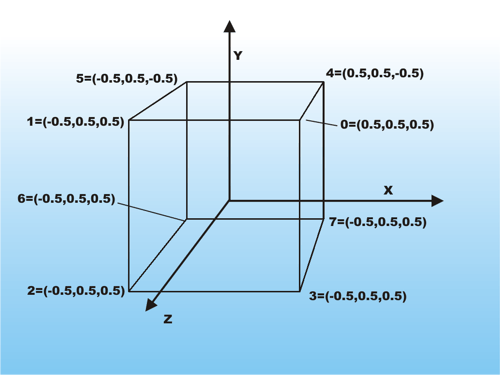
The Media3D namespace is where most of the 3D classes can be found. To get started we need a 3D mesh that can be rendered. The simplest useful mesh you can create is a cube positioned at the origin of the coordinate system. When you first discover how a mesh is defined it seems over-complex. First you need to define an array of all of the points making up the mesh. Then you define triangles by specifying the indices in the point array of the three points that make up each triangle. This allows the same points to be used in different triangles. It is worth keeping in mind that y is up-down, x is left-right and z positive out of the screen, negative into the screen. A function that returns a cubic mesh starts:
First we need to create an array of points. In this case we need eight points corresponding to the eight corners of the cube:
Every mesh stores the array of points it uses in its Positions collection:
The cube and the coordinate system The points are stored in the Positions property of the MeshGeometry3D object. |
|||||
| Last Updated ( Wednesday, 10 June 2015 ) |