| WPF The Easy 3D Way |
| Written by Mike James | |||||
| Wednesday, 10 June 2015 | |||||
Page 2 of 4
Triangles Make A MeshNext we need to define the 12 triangles (two for each of the six faces of the cube) by listing their points in order. The only difficult part of this task is making sure you get the point in clockwise order otherwise you are looking at the back of the face and it doesn't show. It is easier to first initialize an array with the required values:
and then transfer this using a loop to the triangle collection:
This method of defining an array and transferring it is just to shorten the amount of typing needed. You could add the index values directly to the Triangles collection. Finally we set the cube’s TriangleIndices and return it as the result:
A mesh also has a normals collection and a texture coordinate collection which can be used for more realistic effects but this is the simplest mesh and only requires points and triangles

A Renderable ObjectNow that we have a demonstration mesh we can begin to construct the 3D model and its view. The best place for this code is in the Window Loaded event handler. To add the event handler select Window1 in the designer, select events in the property window and double click the Loaded event. All of the drawing instructions are entered into the generated loaded event handler:
Creating the mesh isn’t quite the end of the story. To be rendered a mesh needs to be associated with a “material” which defines its colour and texture. As you are very likely to want to create multiple 3D objects with the same mesh, but perhaps in different colours and textures, it makes sense to use another class which stores a mesh and a material. This is what the GeometryModel3D class does and it is the simplest object that can be rendered. We next create a GeometryModel3D and store the mesh in its Geometry property:
All we need to complete the model is to assign a material:
This makes our cube render in as if it was covered in a matt red paint. There are other types of material and you can apply more complex brushes such as image brushes and the best way to find out how these work is to experiment. The SceneNow we have the 3D object and need to create at least one light and a camera object to view it. Setting up the lighting can be the most difficult part of getting a 3D scene to render. One of the simplest types of lights to use is the directional light. This creates light of a specific colour in a given direction. To create a white directional light shining down, to the left and into the scene you would use:
You can define multiple lights of different types but a single directional light is enough to demonstrate how objects change their appearance in response to lighting. Finally we need a camera. A perspective camera is the most common one to use because it renders a scene complete with perspective effects, but this does make it slightly more complex to define:
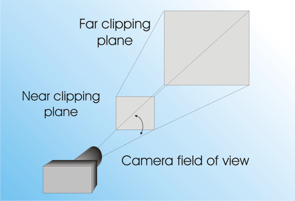
To set the camera we need to specify its near and far clipping planes – any object closer or further way from the camera isn’t rendered:
The camera’s field of view is specified as an angle and corresponds to the angle of the view cone. You can think of this as setting the type of lens the camera is using. A big angle exaggerates perspective and corresponds to a wide-angle lens. A small angle reduces the perspective effect and corresponds to a telephoto lens:
The camera geometry
In this case we need to position the camera at a positive z direction to be in front of the cube and to the right and above the cube (recall the cube is positioned at the origin):
The most difficult camera setting to get right is the LookDirection, i.e. the direction the camera is pointing in. If you get it wrong you the chances of seeing anything are slim. A handy tip to get started is that if you move the camera, which is initially at the origin, to x,y,z then a LookDirection set to –x,-y,-z looks at the origin. As our cube is at the origin we can use this prescription to give:
Finally the camera needs to know which way is up:
If you get this wrong the scene will be rendered at an angle or upside down even.
|
|||||
| Last Updated ( Wednesday, 10 June 2015 ) |