|
Page 1 of 4 GPIO output is easy, input not so much. In this extract from our latest book on using GPIO Zero on the Raspberry Pi in Python, now designated as the default library for all Rapsberry Pi models, we look at how to get started.
Raspberry Pi IoT In Python Using GPIO Zero
Second Edition
By Harry Fairhead & Mike James
Buy from Amazon.
Contents
- Why Pi for IoT?
- Getting Started With Python And GPIO Zero
- Introduction to the GPIO
- Python - Class and Object
- Simple On/Off Devices
Extract 1: On/Off Devices *
- Pins And Pin Factories
Extract 1: Pins
- Some Electronics
- Simple Input
Extract 1:Getting Input ***NEW!!
- Complex Input Devices
Extract 1: Complex Input *
- Pulse Width Modulation
Extract 1: PWM*
- Controlling Motors And Servos
Extract 1: DC Motors *
- Working With Compound Devices
Extract 1: Compound Devices*
- The SPI Bus
- Custom SPI Devices
- Using The Lgpio Library
- Appendix Visual Studio Code Remote Python
*Extracts from first edition - will be updated.
<ASIN:1871962870>
GPIO input is a much more difficult problem than output from the point of view of measurement and verification. For output you can see the change in the signal on a logic analyzer and know the exact time that it occurred. This makes it possible to track down timing problems and fine-tune things with good accuracy. Input, on the other hand, is "silent" and unobservable. When did you read the status of the line? Usually the timing of the read is with respect to some other action that the device has taken. For example, you read the input line 20 µs after setting the output line high. In some applications the times are long and/or unimportant, but in some they are critical and so we need some strategies for monitoring and controlling read events.
The usual rule of thumb is to assume that it takes as long to read a GPIO line as it does to set it.
One common and very useful trick when you are trying to get the timing of input correct is to substitute an output command to a spare GPIO line and monitor it with a logic analyzer. Place the output instruction just before the input instruction and where you see the line change on the logic analyzer should be close to the time that the input would be read in the unmodified program. You can use this to debug and fine-tune and then remove the output statement.
The Button
The GPIO Zero library has only one simple input device – the Button, but for a simple input device it is surprisingly complicated. This is not its fault, but another reflection of the fact that input is hard.

Of course, it doesn’t have to be connected to a button - it can be any device that creates a definite high low signal on a GPIO line. The button could be any sort of switch that is actuated in any way – a reed switch activated by a magnet, a tilt switch activated by angle, and so on.
A reed switch is closed by being near a magnet.

A tilt switch is closed by being rotated until a blob of mercury makes a connection.

The Button has a surprising number of possible parameters:
Button(pin,pull_up=True, active_state=None,
  bounce_time=None, hold_time=1, hold_repeat=False)
at its simplest, however, you only have to provide the pin number:
button = Button(4)
This puts the GPIO line, GPIO4 in this case, into input mode and the defaults are such that a pull-up is automatically used, see previous chapter. This means that you can wire a switch to GPIO4 without the need for any other components.
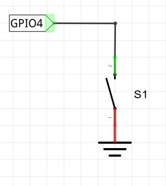
Ground is pin 6 and GPIO4 is pin 7.
If you want to use a pull-down arrangement, set pull_up to False when you create the pin.
|