In other words the first time the line is pulled high and released it remains high when it should be pulled low by the pull down resistor. This stops many programs working – in particular the open collector program given earlier doesn’t work in a pull-down configuration:
#include "pico/stdlib.h"
int main()
{
    gpio_set_function(22, GPIO_FUNC_SIO);
    gpio_pull_down(22);
    gpio_set_dir(22, false);
    gpio_put(22,1);
    volatile int temp;
    while (true)
    {
      gpio_set_dir(22, true);
      for(temp=0;temp<2000;temp++){};
      gpio_set_dir(22, false);
      for(temp=0;temp<2000;temp++){};
    }
  }
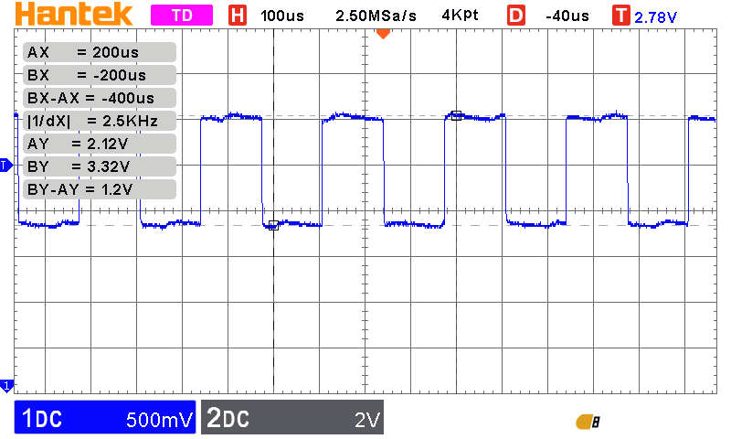
This should generate a pulse train similar to the one produced by the pull up version but if you view it on a logic analyzer the output remains high. If you view it on an oscilloscope then what you see is:
The output is changing but between 3.3V and 2.12V rather than 3.3V and 0V and 2.12V is regarded as a logic one hence the logic analyzer doesn’t see it.
What is the solution?
The best solution would be for Raspberry Pi to fix the flaw in the input stage of the PAD but until that happens you can either change your software or the hardware.
The software solution is to turn off the input buffer and reenable input before reading the line. A function to set the input buffer enable bit is:
A much better solution is to not use the internal pull-down resistor. If you look back at the diagram with the load lines drawn on it you can see that a 10k resistor has a load line that just misses the negative differential resistance part of the curve. This means that for this value and lower of pull down resistor there is only one stable equilibrium i.e. 0V. The documentation suggests 8k or smaller. This gives a pull-down current of 412 µA which is small enough for most applications. Notice that the problem isn’t with the pull-down resistor but with the input buffer stage and if you use an external resistance of around 80k then you will get the same behavior.
The documentation also states that the problem does not occur with a pull-up resistor as the input buffer sources leakage current rather than sinking it and so the pull-up succeeds in setting the line to 3.3V. Notice that if you use a potential divider with two resistors the lower resistor acts like a pull-down and this might trigger the same behavior.
The problem extends to all of the available user GPIO lines but not to the QSPI pads or the USB pins. It does however effect the GPIO line in all of the usual modes including PIO. In this case the simplest and most robust solution is to use an external pull-down resistor of at most 8k.
To summarize:
All of the user GPIO lines have additional leakage current in input mode.
If you are using a pull-down resistor of more than around 10k then the pull-down may not return to 0V but latch into a stable state at around 2.2V.
This is true for the internal pull-down resistors – don’t use them.
The latched state is read as a 1 and hence makes working with an open emitter bus impossible.
Pull-up configurations are not effected but there is still additional leakage current.
If you have to use pull-down mode use an external resistor of at most 8k.
In chapter but not in this extract
Drive, Slew and Schmitt
Basic Input Circuit - The Switch
Debounce
The Potential Divider
Summary of Chapter
You can get a long way with only a small understanding of electronics, but you do need to know enough to protect the Pico and things you connect to it.
The maximum current from any GPIO line should be less than 12mA and the total current should be less than 30mA.
All of the GPIO lines work at 3.3V and you should avoid directly connecting any other voltage.
You can drive an LED directly from a GPIO line, but only at 16mA rather than the nominal 20mA needed for full brightness.
Calculating a current-limiting resistor always follows the same steps – find out the current in the device, find out the voltage across the device and work out the resistor that supplies that current when the remainder of the voltage is applied to it.
In many cases you need a transistor, a BJT, to increase the current supplied by the GPIO line.
To use a BJT you need a current-limiting resistor in the base and generally one in the collector.
MOSFETs are popular alternatives to BJTs, but it is difficult to find a MOSFET that works reliably at 3.3V.
GPIO output lines can be set to active push-pull mode, where a transistor is used to pull the line high or low, or passive pull-up or pull-down mode, where one transistor is used and a resistor pulls the line high or low when the transistor is inactive.
When used as inputs, GPIO lines have a very high resistance and in most cases you need pull-up or pull-down resistors to stop the line floating. The Pico 2 has a defect that reduces its high resistance.
The built-in pull-up or pull-down resistors can be used in input or output mode.
The Pico 2 has a fault in that GPIO lines leak more current than they should and this makes using the internal pull-down difficult.
Mechanical input devices have to be debounced to stop spurious input.
If you need to connect an input to something bigger than 3.3V then you need a potential divider to reduce the voltage back to 3.3V. You can also use a transistor.
Programming the Raspberry Pi Pico In C Third Edition