| Pi IoT In Python Using GPIO Zero - Complex Input |
| Written by Harry Fairhead & Mike James | ||||
| Monday, 18 January 2021 | ||||
Page 2 of 3
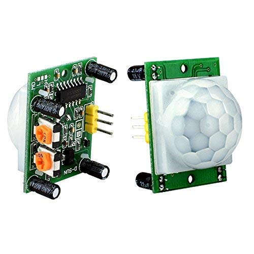
D-SUN PIR Motion SensorInfrared motion detectors work by sensing a change in the level of infrared radiation. The D-SUN PIR is a standard low-cost module, but you can use any that follow the basic design with a three-pin connection – Vcc, Ground and Data. The data line is set high when motion is detected. Different devices have different controls for sensitivity and usually a setting for repeatable or non-repeatable mode. In repeatable mode the output goes high when motion is detected and the device is reset after a set time so that it is ready to detect motion again. In non-repeatable mode the output is set high as long as motion is detected.
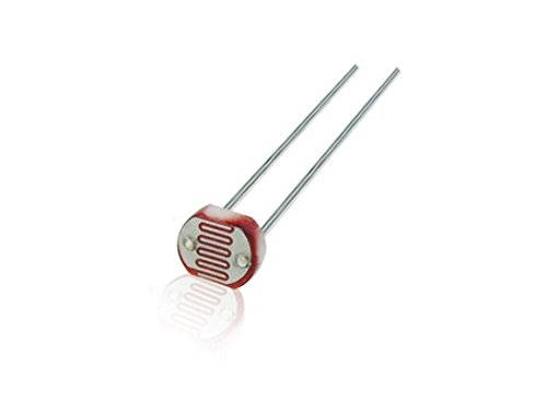
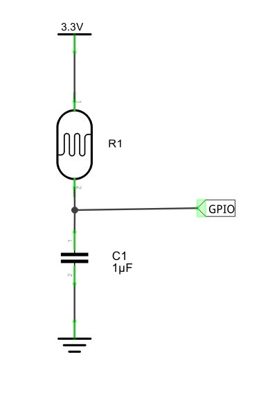
To use the device all you have to do is connect the Vcc pin to 5V, the ground pin to ground and the data pin to the GPIO line you want to use. You can create a MotionSensor object using the constructor: MotionSensor(pin, *, queue_len=1, sample_rate=10, Notice that the default for queue_len is 1, meaning that no smoothing is performed. To discover if motion has been detected you can use value or motion_detected which compares value to the threshold. You can also use the wait_for_motion, wait_for_no_motion, when_motion and when_no_motion events. LDR Light SensorThere are many different types of light sensor, but the LDR, Light Dependent Resistor, is one of the simplest. As its name suggests, it simply changes its resistance according to how much light falls on it. Using it to sense the light level is simply a matter of measuring its resistance. This can be done directly, but you can also use the resistance to change other physical properties of a system. For example, you can charge a capacitor to a set voltage and then time how long it takes to discharge through the resistor. This is how the LightSensor class works. You need to set up the simple circuit shown below. What happens is that, when a reading is required, the GPIO line is set to low, which discharges the capacitor. Then it is set to input, which allows the capacitor to charge through the LDR. The GPIO line reads 0 until the capacitor has charged enough to make it read 1. The time to read 1 is proportional to the resistance, which in turn is proportional to the light falling on it.
The only problem we have is that different LDRs have different resistances and hence different charge times. You can work out the charge times, but the simplest thing to do is to adjust the time by trial and error. Once you have the circuit connected to the GPIO line of your choice, you can create a LightSensor object using the constructor: LightSensor(pin, *, queue_len=5, charge_time_limit=0.01,
threshold=0.1, partial=False, pin_factory=None)
The new element here is the charge_time_limit which is the time in seconds it takes the capacitor to charge enough to change the zero input to a one. The default should be close to the value you need, but you might have to tune it by trial and error to the range of light inputs that you want to work with, i.e. what you consider light and what you consider dark. Also notice that by default five readings are taken. An LDR changes its resistance slowly in response to a sudden light change. You can use the light_detected property to see if the light exceeds the threshold or the value property to measure the light level. You can also use the wait_for_dark, wait_for_light, when_dark and when_light events. |
||||
| Last Updated ( Monday, 18 January 2021 ) |