| The Pico In MicroPython: A PIO Driver For The DHT22 |
| Written by Harry Fairhead & Mike James | ||||||||||||
| Monday, 17 May 2021 | ||||||||||||
Page 2 of 3
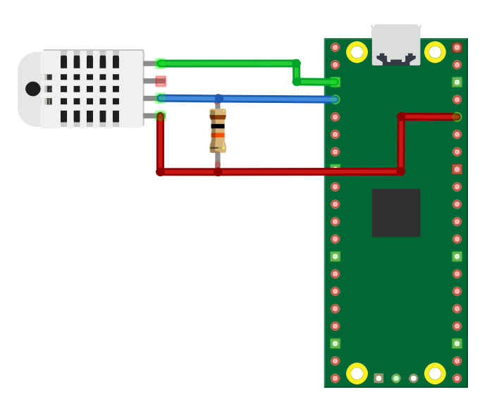
The ElectronicsExactly how you build the circuit is a matter of preference. The basic layout can be seen below.
It is very easy to create this circuit using a prototyping board and some jumper wires. You can also put the resistor close to the DHT22 to make a sensor package connected to the Pico using three cables. In chapter but not in this extract:
DHT22 Using the PIO – SamplingA simpler alternative way for decoding the data is to ignore the fact that it is the width of each bit’s frame that defines a zero, a short frame, or a one a long frame, and notice that if you sample at a suitable fixed time from the rising edge of a pulse then you will get a zero in a zero frame and a one in a one frame: You can see the sampling times from the pulses on the lower trace of the logic analyzer and the fact that you do indeed get a 0 in a zero frame and a 1 in a one frame. You can also see that the time to sample from the rising edge is constant, even if the sampling period varies. Surprisingly, the PIO program to implement this sampling isn’t significantly simpler than the previous program, but the entire four data bytes can now be packed into a single FIFO entry and the checksum byte can occupy a second entry. The PIO program starts off in the same way: .program dht
set pins, 1
set pindirs, 1
The waits’ position is at the state of the data and now we can wait for a rising edge and then delay until the sample time: set y,31
bits:
wait 1 pin 0 [25]
in pins,1
wait 0 pin 0
jmp y--,bits
This too is very similar, only now we don’t keep a count but simply add the single bit sampled from the input line to the ISR. When all 32 bits have been added, the autopush moves the data to the FIFO. The eight checksum bits are just as easy to process and the complete PIO program is: .program dht set pins, 1 set pindirs, 1 again: pull block set pins, 0 mov x, osr loop1: jmp x--,loop1 set pindirs, 0 wait 1 pin 0 wait 0 pin 0 wait 1 pin 0 wait 0 pin 0 set y,31 bits: wait 1 pin 0 [25] in pins,1 wait 0 pin 0 jmp y--,bits set y,7 check: wait 1 pin 0 [25] in pins,1 wait 0 pin 0 jmp y--,check push block jmp again Notice that we have to manually push the ISR because it doesn’t fill up just the 8 bits of the checksum. The MicroPython program is also very like the previous program, but we have to change the clock frequency and the shift direction to make decoding the bytes from the 32-bit word easier. We need a slower clock speed to make the delay position the sample point about 50µs from the rising edge – recall that the delay is limited to 32 clock cycles. The getReading method now might as well read the FIFO and decode the data directly as it is a much simpler task: def getReading(self):
self.sm.put(500)
data=0
data = self.sm.get()
byte1 = (data >> 24 & 0xFF)
byte2 = (data >> 16 & 0xFF)
byte3 = (data >> 8 & 0xFF)
byte4 = (data & 0xFF)
checksum = self.sm.get() & 0xFF
Notice the need to change the value sent to the input to account for the slower clock rate – 500 now produces a 1ms initialization pulse. The rest of the program is unchanged as we now have the four data bytes and the checksum as before. This program is simpler to implement and can be extended to a protocol that needs to read in more than 40 bits at a time. |
||||||||||||
| Last Updated ( Monday, 17 May 2021 ) |