| Pi IoT In Python Using Linux Drivers - I2C |
| Written by Harry Fairhead & Mike James | ||||||||||||||||||||||||||||||||||||||
| Monday, 01 November 2021 | ||||||||||||||||||||||||||||||||||||||
Page 2 of 4
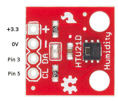
A Real Device - HTU21DUsing an I2C device has two problems - the physical connection between master and slave and figuring out what the software has to do to make it work. Here we’ll work with the SparkFun HTU21D/Si7021 and the information in its datasheet to make a working temperature and humidity sensor using the I2C functions we’ve just met. First the hardware. The HTU21D Humidity and Temperature sensor is one of the easiest of I2C devices to use. Its only problem is that it is only available in a surface-mount package. To overcome this you could solder some wires onto the pads or buy a general breakout board. However, it is much simpler to buy the SparkFun HTU21D breakout board because this has easy connections and built-in pull-up resistors. The HTU21D has been replaced by the Si7021 which is more robust than the original and works in the same way although the HTU21D is still available from many sources. If you decide to work with some other I2C device you can still follow the steps given, modifying what you do to suit it. In particular, if you select a device that only works at 5V you might need a level converter. It is worth noting that there is a specific Linux driver for the HTU21D. This is described in Chapter 14 and in most cases is the preferred way to use the device. To provide a generalizable example, here we look at exactly how the device works on the I2C bus and a program that interfaces with it at a low level is described. Wiring The HTU21DGiven that the HTU21D has pull-up resistors, we really should disable them for use on the Pi’s internal I2C bus which already has pull-ups. In practice, the additional pull-ups don't seem to make much difference to the waveforms and you can leave them in place while testing. You can use a prototype board to make the connections and this makes it easier to connect other instruments such as a logic analyzer.
A First ProgramAfter wiring up any I2C device, the first question that needs to be answered is, does it work? Unfortunatel,y for most complex devices finding out if it works is a multi-step process. Our first program aims to read some data back from the HTU21D - any data will do. If you look at the datasheet you will find that the device address is 0x40 and its supports the following commands/registers:
For example to read the user register: import subprocess
import io
import fcntl
def checkI2CBus():
temp = subprocess.Popen(["sudo", "dtparam", "-l"],
stdout = subprocess.PIPE)
output = str(temp.communicate())
lasti2c=output.rfind("i2c_arm")
if lasti2c!=-1:
lasti2c=output.find("i2c_arm=on",lasti2c)
if lasti2c==-1:
temp = subprocess.Popen(["sudo", "dtparam",
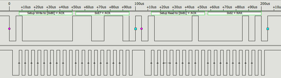
This sends the address frame 0x80 and then the data byte 0xE7 to select the user register. Next it sends an address frame 0x81 to read the data. If you run the program you will see: b'\x02' This is the default value of the register and it corresponds to a resolution of 12 bits and 14 bits for the humidity and temperature respectively and a supply voltage greater than 2.25V. I2C Protocol In ActionIf you have a logic analyzer that can interpret the I2C protocol connected what you will see is:
You can see that the write_byte function sends an address packet set to the device's 7-bit address 0x40 as the high order bits with the low order bit set to zero to indicate a write, i.e 0x80. After this you get a data packet sent containing 0xE7, the address of the register. After a few microseconds it sends the address frame again, only this time with the low order bit set to 1 to indicate a read, i.e. it sends 0x81. It then receives back a single byte of data from the device, 0x02. This demonstrates that the external device is working properly and we can move on to getting some data of interest. Reading Raw Temperature DataNow we come to reading one of the two quantities that the device measures – temperature. If you look back at the command table you will see that there are two possible commands for reading the temperature:
What is the difference between Hold master and No Hold master? This was discussed earlier in a general context. The device cannot read the temperature instantaneously and the master can either opt to be held waiting for the data, i.e. hold master, or released to do something else and poll for the data until it is ready. The simplest thing to do is poll for the data. In this case we send F3 and then wait for there to be something to read. If the slave isn't ready it simply replies with a NAK and this causes the read to throw an exception that we catch using a try-catch: fdw.write( bytearray([0xF3]))
while(True):
try:
data=fdr.read(3)
break
except:
sleep(0.01)
This polls repeatedly until the slave device returns an ACK when the data is loaded into the master. |
||||||||||||||||||||||||||||||||||||||
| Last Updated ( Wednesday, 23 November 2022 ) |