| Pi IoT In Python Using GPIO Zero - PWM |
| Written by Harry Fairhead & Mike James | ||||
| Monday, 28 February 2022 | ||||
Page 2 of 3
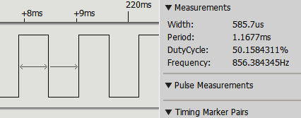
The alternative to dedicated PWM hardware is to implement it in software. You can quite easily work out how to do this. All you need is to set a timing loop to set the line high at the repetition rate and then set it low again according to the duty cycle. You can implement this either using interrupts or a polling loop and in more advanced ways, such as using a DMA (Direct Memory Access) channel. In the case of the Pi, the PWM lines are implemented using special PWM hardware but, as already mentioned, at the time of writing, none of the pin factories supports using hardware PWM. The standard RPi.GPIO factory supports software-implemented PWM on any GPIO pin and this is the factory used in the rest of this chapter. As you can guess, there are no PWM inputs, just output. If for some reason you need to decode, or respond to, a PWM input then you need to program it using the GPIO input lines and the pulse measuring techniques introduced in previous chapters. Using PWMThe direct way of using PWM is to create an instance of the PWMOutputDevice class, yet this is listed as a base class as if it wasn’t to be used in everyday programming. This couldn’t be further from the truth and, if you hope to do anything even slightly innovative you need to know about PWMOutputDevice. There is no real excuse as it is very easy to use. If you create an instance, using GPIO4 say: pwm=PWMOutputDevice(4) then there are just two important properties, frequency and value. The frequency property sets the PWM repeat rate and value sets the duty cycle as a fraction. For example: pwm.frequency=1000 pwm.value=0.5 sets a frequency of 1kHz and a duty cycle of 0.5, i.e. 50%. Putting this together gives: from gpiozero import PWMOutputDevice from signal import pause pwm=PWMOutputDevice(4) pwm.frequency=10000 pwm.value=0.5 pause() Notice that you have to use pause to keep the program running as the PWM isn’t hardware-generated. The program has to be “doing something”, even if it is only sleeping so that it can update the PWM state. If you look at the signal using a logic analyzer you will be dismayed to discover that it isn’t a 1kHz signal:
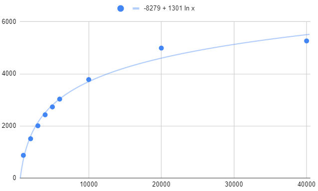
As in most cases the duty cycle is what is important, not the frequency, an inaccuracy of 150Hz may not matter. For the Pi Zero you need to specify a frequency roughly 20% greater than you need. For example, a frequency of 1200Hz gives a PWM signal of 1000Hz within a few Hertz. A plot of specified frequency versus actual for the Pi Zero reveals that 6kHz is as fast as you can go:
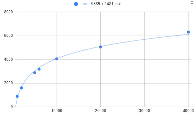
The plot for the Pi 4 is very similar:
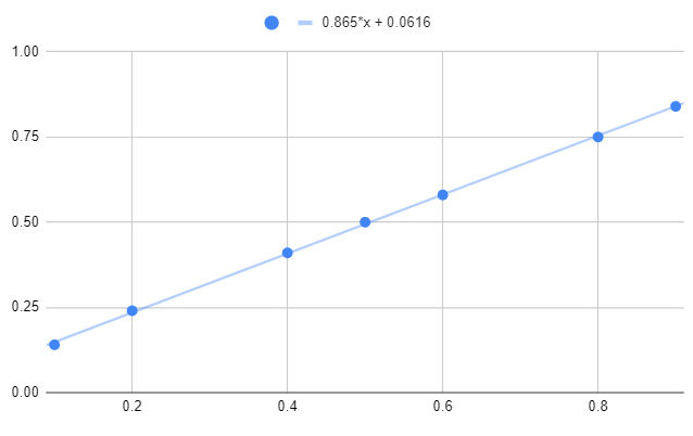
Comparing this performance to hardware-generated PWM, it is slow. However, for many applications this doesn’t matter. For example, to use PWM to control a servo you only need a frequency of 50Hz. The problem with the frequency error also occurs in the setting of the duty cycle. The software detects duty cycles of 0 and 1 and correctly sets the line low or high respectively. However, for values close to 0 or 1 you get a duty cycle longer or shorter than requested. The results for a Pi 4 and Pi Zero are very similar:
Notice that there is a sudden jump to duty cycles of 0 and 1 which isn’t shown in the graph. |
||||
| Last Updated ( Monday, 28 February 2022 ) |