| The Pico In MicroPython: DC Motors |
| Written by Harry Fairhead & Mike James | |||||||||||||||||||||||
| Friday, 18 March 2022 | |||||||||||||||||||||||
Page 1 of 2 One of the very basic control tasks is running a DC motor. This usually involves some hardware as well as software. This is an extract from our book all about the Raspberry Pi Pico in MicroPython. Programming the Raspberry Pi Pico/W In MicroPython Third EditionBy Harry Fairhead & Mike James
Buy from Amazon. Contents
Also of interest: **** articles from the second edition not yet updated. <ASIN:B0BR8LWYMZ> <ASIN:B0BL1HS3QD> Controlling motors is an obvious use for the low cost Pico, but it is important to understand the different types of motor that you can use and exactly how to control them using PWM. In addition to PWM control, we also look at the very useful stepper motor which doesn’t make use of PWM. The simplest division among types of motor is AC and DC. AC motors are generally large and powerful and run from mains voltage. As they are more difficult to work with, and they work at mains voltages, these aren’t used much in IoT applications. DC motors generally work on lower voltage and are much more suitable for the IoT. In this chapter we will only look at DC motors and how they work thanks to pulse width modulation. The parts used are listed in the Resources section of the book’s webpage at www.iopress.info. DC MotorThere are two big classes of DC motor – brushed and brushless. All motors work by using a set of fixed magnets, the stator, and a set of rotating magnets, the rotor. The important idea is that a motor generates a “push” that rotates the shaft by the forces between the magnet that makes up the stator and the magnet that makes up the rotor. The stronger these magnets are, the stronger the push and the more torque (turning force) the motor can produce. To keep the motor turning, one of the two magnetic fields has to change to keep the rotor being attracted to a new position. DC motors differ in how they create the magnetism in each component, either using a permanent magnet or an electromagnet. This means there are four possible arrangements:
Arrangement 1 can’t produce a motor because there is no easy way of changing the magnetic field. Arrangement 4 produces the biggest and most powerful DC motors used in trains, cars and so on. Arrangement 2, Brushed DC, is the most commonly encountered form of “small” DC motor. However, arrangement 3, brushless DC, is becoming increasingly popular. Different arrangements produce motors which have different torque characteristics, i.e. how hard they are to stop at any given speed. Some types of motor are typically low torque at any speed, i.e. they spin fast but are easy to stop. Low torque motors are often used with gearboxes, which reduce the speed and increase the torque. The big problem with gearboxes, apart from extra cost, is backlash. The gears don’t mesh perfectly and this looseness means that you can turn the input shaft and at first the output shaft won’t move. Only when the slack in the gears has been taken up will the output shaft move. This makes a geared motor less useful for precise positioning, although there are ways to improve on this using feedback and clever programming. Brushed MotorsTo energize the electromagnets, a brushed motor supplies current to the armature via a split ring or commutator and brushes. As the rotor rotates, the current in the coil is reversed and it is always attracted to the other pole of the magnet. The only problem with this arrangement is that, as the brushes rub on the slip ring as the armature rotates, they wear out and cause sparks and hence RF interference. The quality of a brushed motor depends very much on the design of the brushes and the commutator.
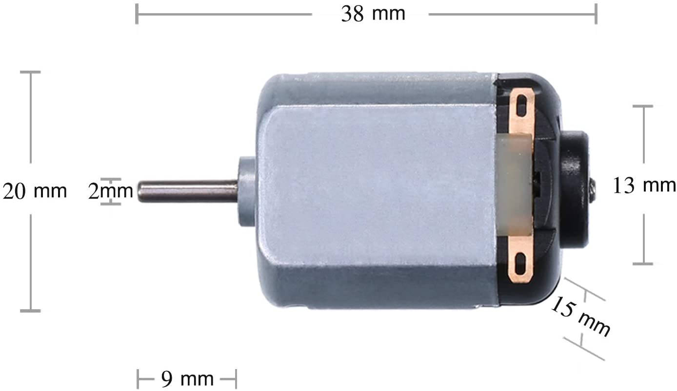
Very small, cheap, brushed DC motors, of the sort in the picture below, tend to not have brushes that can be changed and when they wear out the motor has to be replaced. They also tend to have very low torque and high speed. This usually means that they have to be used with a gearbox. If you overload a brushed motor then the tendency is to demagnetize the stator magnets. The cheapest devices are basically toys.
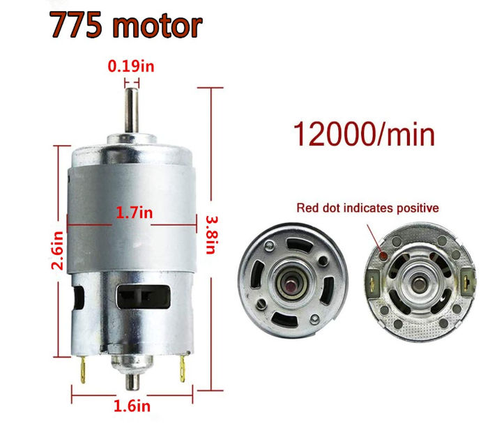
Higher quality brushed motors are available and they also come in a variety of form factors. For example, the 775 motor is 66.7 by 42mm with a 5mm shaft: Even these motors tend not to have user-serviceable brushes, but they tend to last a long time due to better construction. |
|||||||||||||||||||||||
| Last Updated ( Friday, 18 March 2022 ) |