| Exploring Edison - Meet Edison |
| Written by Harry Fairhead | ||||
| Tuesday, 02 June 2015 | ||||
Page 2 of 3
Standard Breakout BoardsThe Edison has 40 GPIO connections - some of which have special roles like acting as a serial interface or a interfacing to an SD card. In a finished product you would wire directly to the 70-pin connector via your custom breakout board, but for prototyping you need something to give you access while you experiment.
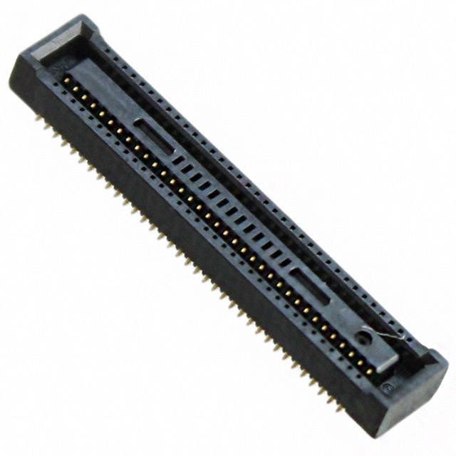
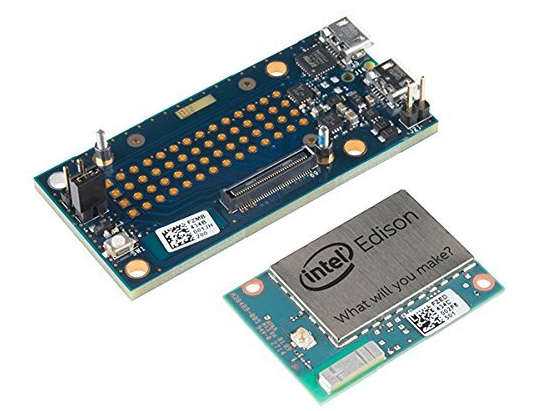
The 70-pin connector brings out the GPIO lines, a USB port and the power lines. As already mentioned the connector is very small 70-pin Hirose DF40 and with 0.4 mm contact pitch it is very difficult to solder to directly.
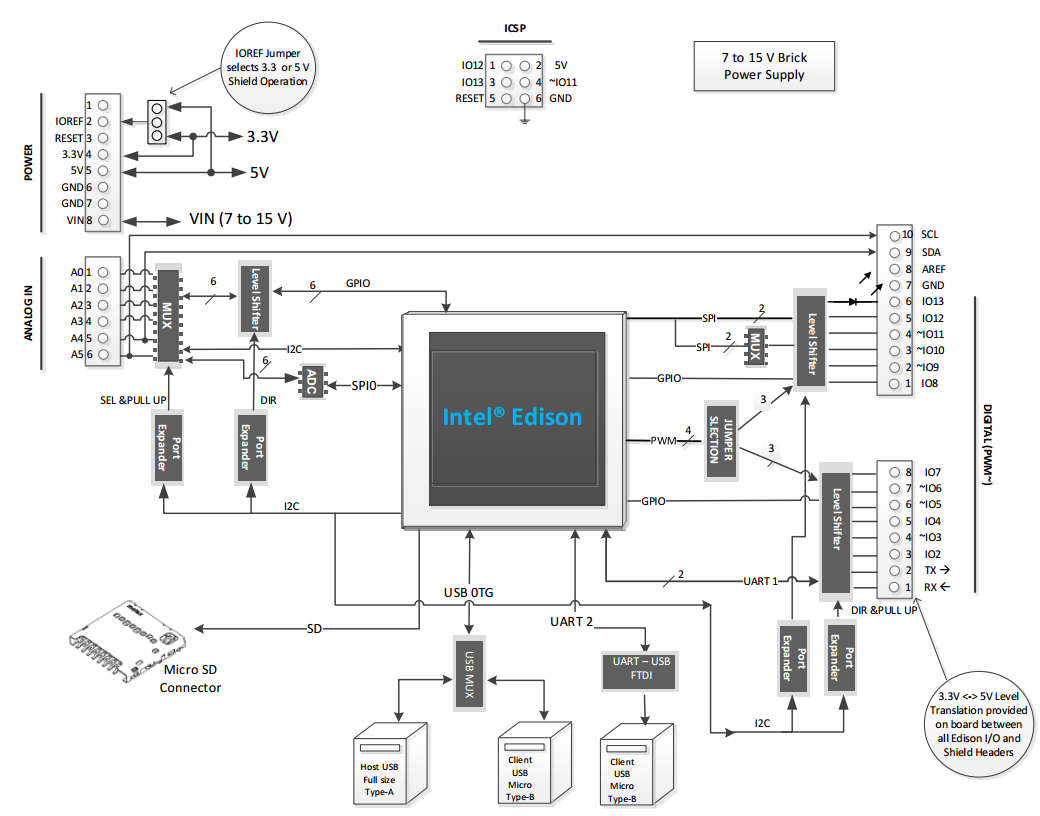
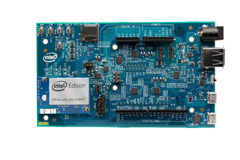
The solution is to use a breakout board which accepts the Edison and provides power and other facilities. It is worth mentioning at this early stage that the Edison uses 1.8V logic so you can't simply attach an LED say and expect to toggle it on and off. The problem of converting the 1.8V logic levels to something more familiar is something that a breakout board can tackle. There are two standard breakout boards from Intel and a number of similar ones from other sources - for simplicity let's look at the Intel boards. Arduino BreakoutThe first is the Arduino breakout board. This as its name suggests takes the GPIO connections from the Edison and converts them both electrically and physically to the outputs you would find on the Arduino. So exact is this mapping that you can actually use Arduino shields to expand the Edison.
When installed on an Arduino breakout board the Edision looks a lot like the Intel Galileo but with WiFi. This similarity between the Edison+Arduino board and Galileo explains why you will often find software and documentation covering both - however there are some differences, such as the WiFi. In most cases what works for the Galileo should work with the Edison plus Arduino breakout board.
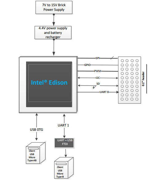
The Arduino breakout board is easy to use. Especially so if you already have Ardunio experience. The reason is that one of the possible programing environments for the Edison is the Arduino IDE which allows you to write programs as if you were working with a real Arduino. That is the Arduino breakout board allows you to treat the Edison as if it was an Arduino for much of the time - for both hardware an software. It also provides lots of extras that make getting started with the Edison easier. In particular it provides logic level translation from 1.8V to the more familiar 5V. This allows you to directly connect and flash LEDs and use the sensors output devices that you might well be familiar with. Of course if you are thinking of creating a custom device based on the Edison then the Arduino board may present you with a small problem. It implements electronics to convert the Edison's GPIO to the Arduino pin out. If you want to move on from using the breakout board then you are going to have to duplicate any of the electronics on the breakout board that supports Arduino features that you want to use that aren't native. For example if you make use any of the AtoD converter pins then you have to implement one on your custom board. This isn't as difficult as it sounds because Intel have provided that full schematic of the Arduino breakout board and you can use this as the basis for your own. Edison (Mini) BreakoutUsing the Edison as an Arduino has lots of advantages but there are times when the project you have in mind really doesn't need the fairly elaborate hardware that is used to implement the Arduino pin outs. In these cases it is better to make use of the much smaller Edison Breakout board - sometimes called the "mini breakout" board. You can see from a block diagram this is a very much simpler breakout board than the Arduino board:
While the USB and power have some electronics dedicated to making them easier to use, the GPIO lines are brought out directly to a 0.1 inch header. Notice that you don't actually get any pins to connect to just the solder pads. How to deal with this is something discussed in later chapters. Also notice that there is no SD card - if you want to support an SD card you have to add some electronics to the SD lines available on the header. The board is also much smaller than the Arduino breakout and more in keeping with the whole Edison ethos:
In summary: the mini breakout board has all you need to power and talk to the Edison but it makes no effort to convert the Edison GPIO to anything at all. What you do get is the large header space on the bottom of the board. This is very easy to work with and you can make connection to a prototype board via jumper wires. What you do with the signals next is up to you, but it is worth mentioning again that the native logic level for the Edison is 1.8V and its current drive is just 3mA. In other words, these are not TTL or CMOS levels of the sort you encounter in the Arduino and the Raspberry Pi. For example, you can't just connect an LED to a pin and expect to be able to switch it on and off - the voltage is too low and there isn't enough drive current. It might work if you are lucky to use an LED with a low drive demand but you cannot rely on it. If you want to use a 5V sensor then this low voltage logic makes things more difficult, but many modern sensors use, or can use, a 1.8V logic level. The advantage of working with such low voltages is that the sensors and other devices use a lot less power. If you do want to use your favourite 5V sensor or output device then you are going to have to get used to implementing level shifting and drivers and this is something we have to tackle. It turns out to be not a huge problem and once you have settled down with 1.8V logic it is as easy to live with as TTL or CMOS levels. You can also use the Arduino IDE to develop software using the Arduino IDE for the mini breakout board. However in most cases it makes more sense to program your applications using C or Python, or even JavaScript and leave the Arduino behind. You can use these languages with the Arduino IDE and move your programs over to the mini breakout board very easily. In this way you can develop your code and be sure it works before you have to implement the custom hardware needed to make the mini breakout board work properly. For example if you want to create a new serial protocol using a GPIO line then you can use the Arduino board as a level shifter to 5V and develop your software. Then knowing it works you can move to the mini breakout board and implement a 5V level shifter. If you use any of the features of the Arduino board such as the AtoD converters then again you can be sure you software works and all you have to do is implement an AtoD in hardware for use with the mini breakout. In short the Arduino breakout board makes a good test bed for your mini breakout projects, which in turn makes a good test bed for your final production device.
|
||||
| Last Updated ( Monday, 29 June 2015 ) |