| Exploring Edison - Fast Memory Mapped I/O |
| Written by Harry Fairhead | |||||||||||||||||||
| Wednesday, 23 September 2015 | |||||||||||||||||||
Page 3 of 4
Fast InputNow we have to try to answer the question of how fast a pulse Edison can measure on input. Input is more difficult to quantify because you have to take potentially many measurements to track an input pulse. There is no point in trying to use an interrupt approach because interrupts always make use of SYSFS and this is slow. If you want the advantages of memory mapped I/O you have to use a polling loop. A simple measurement of how long it takes to perform multiple reads from a single input line gives a reasonable estimate of how fast input can be. Using SYSFS you can read the line 100 times in about 1300 microseconds which is made up of about a 250 microsecond overhead and 10 microseconds per sample, Using memory mapped input you can read 100 times in about 70 microseconds which is made up of about 11 microseconds overhead and 0.68 microseconds per sample. With these estimates it should be possible to read in pulse trains consisting of 10 microsecond pulses using memory mapped input and 100 microsecond pulses using SYSFS. Putting this another way for a 10 microsecond pulse memory mapped input should allow you to get 15 samples per pulse allowing you to time it with an accuracy of about 0.5 microseconds. There are two ways of reading data even using a polling loop. You can opt to use the system to time how long an input hasn't changed with something like:
The problem with this approach is that the realtime clock might claim to be accurate to nanosecond but it isn't. In fact on the Edison it is too coarse to be used to measure the smallest pulses that the Edison is capable of. There is also the fact that the call to clock_gettime takes around 4 microseconds per call and this is a lot to spend when you are working at the 10 microsecond region. A much better idea is to simply use a busy wait implemented as a for loop and use the value of the index when the loop is exited as a measure of time. Use something like:
This also has the advantage that the value that you set for the maximum number of loops i.e. 10,000 in this example acts as a timeout. The value of i when the loop exits gives you a measure of how long the line was low for. Using this simple construction we can easily write a program that measures the length of a high pulse. This is a tiny bit more complicated than you might expect because we only want to measure a single pulse in a uniform pulse train. The algorithm is to first wait for the line to go low. Then wait for it to go high and then wait for it to go low keeping the count of the number of times the loop iterated. That is - wait for the line to go low:
Next wait for the line to go high:
Finally wait for the line to go low again:
The width of the pulse is given by the value of i when the final loop exits. Notice that the count in the final loop starts from 1 because we can count the single high sample that ended the second loop as the first high measurement. The complete program to measure a single pulse and display the "time" in the Eclipse console is:
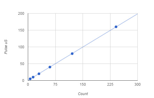
If you feed a range of pulse widths into the input line you can obtain a calibration chart:
You can use the approximate formula:
to convert from final loop count to time in microsecond. This means that if you are trying to measure a 5 microsecond pulse you can expect to get six samples while it is high giving an accuracy of something like 1 microsecond. The number of samples for various sizes of pulse are:
Getting 6 samples per pulse isn't great but it is enough to tell the difference between a 5 and 10 microsecond pulse. Notice also that you can't afford to do any computation in the measuring loop othewise you will reduce the sampling rate. If you are measuring the time the pulse is high there is usually more time to do things in the low part of the pulse because you don't care as much exactly when you start the polling loop - as long as it is before the pulse goes high again. Direct Memory MappingIt was mentioned earlier that it was possible to by-pass mraa and write to the GPIO directly - surely this must be faster? Mostly to avoid you wasting time here is a program that works directly with the in memory driver - and it is no faster than going via mraa. This is a puzzle. Rather than modifying mraa to get the information we need to locate the memory mapped driver it is easier to create a function that loads the driver:
This function is essentially a modified version of how mraa loads the driver. The driver is a file in /sys/devices which is opened and then loaded using the mmap function. The function returns mmap_reg which gives the location of the driver in memory. This is essentially what a call to mraa_gpio_use_mmaped does the first time you call it. As always to make the logic clear no error detection code has been included. The most likely error is that the file is missing or has changed its name due to an update. Now we have the driver loaded into memory we have to work out various addresses and two masks. The address we need depends on the pin number:
This gives the start address of the area that controls the pin - note that the pin number is the SYSFS pin number not the mraa number. We also need two offsets from the start of the area - one for pin on and one for pin off:
Finally we need a mask that is written to the location to change the state of the pin - this also depends on the pin number:
Finally we can actually write to the pin:
to set it high and
to set it low. <ASIN:B00ND1KH42@COM> <ASIN:B00ND1KNXM> <ASIN:B00ND1KH10> |
|||||||||||||||||||
| Last Updated ( Tuesday, 10 May 2016 ) |