| Exploring Edison - Bit Banging the DHT11/DHT22 |
| Written by Harry Fairhead | |||||||||||||||||||
| Monday, 25 January 2016 | |||||||||||||||||||
Page 2 of 3
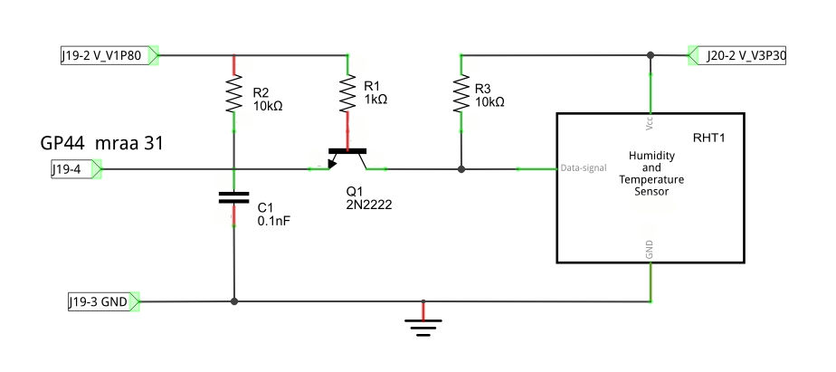
The ElectronicsTo convert the 3.3V device to work with the 1.8V Edison we can make use of the single transistor level shifter introduced in the previous chapter: The pins used on the Edison connector are:
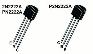
It is worth recalling that for the mini-board you can't alter the output mode of a line using mraa. By default the output mode is pull up with a 50K resistor which is effectively in parallel with our 10K pull up. This means the actually pull up in use is effectively around 8K. If you use a 2N2222 transistor then the pin outs are:
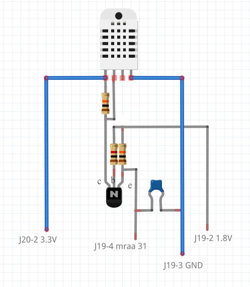
You can build the circuit on a prototype board to test the software but it is also fairly easy to build a free standing circuit on the DHT22 effectively converting it to 1.8V operation:
Isolate the components from one another using heat shrink sleeving. Of course the disadvantage is that now we have a four lead device and the cable cannot be as long - if it is long remove the capacitor as the lead will provide more capacitive loading than you need. The SoftwareWith the hardware shown above connected to the Edison the first thing that we need to do is establish that the system is working - just a little. The simplest way to do this is to pull the line down for 1ms and see if the device responds with a stream of pulses. These can be seen on a logic analyser or an oscilloscope - both are indispensable tools. If you don't have access to either tool then you will just have to skip to the next stage and see if you can read in some data. The simplest program that will do the job is:
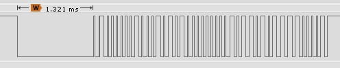
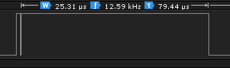
Setting the line initially high we then set it low, wait for 1000 microseconds and then change its direction to input ready to read the data. Notice that we don't have to set the mode of the output line as it can drive its side of the buss safe in the knowledge that the device will not try to drive it until it releases the low state and changes to a high impedance input. As long as the circuit has been correctly assembled and you have a working device you should see something like:
Notice that the pulling low of the line actually lasts 1,3ms which is a bit on the long side but does no harm. If you haven't used the capacitor in the level shifting circuit then you might see on some of the pulses on the Edison's side look something like:
This is caused by the change in operating mode of the transistor. The capacitor acts as a high pass filter and smooths the glitch out. You might not see this effect even without the capacitor because often the circuit layout provides enough stray capacitance to smooth things out. Too much capacitance and the rise time of the pluses is compromised.
Reading The DataWith preliminary flight checks complete it is time to read the 40-bit data stream. When doing this there are two things to keep in mind. The first is that it is only the time the line is high that matters and you need to measure just this accurately - you don't care so much about how long the line is low for. The second is that it is usually better to collect the bits and only later process them and extract the data. To this end it is usually a good idea to save the data in a buffer:
You should be able to see how this works. The outer for loop repeats to read in all 41 bits, 40 data bits and the inital start bit. The inner loop waits for the line to go high and i gives the time that the line has been low. This is of no interest. Next the second for loop waits for the line to go low. The count in i is now proportional to the time the line was high and is stored in the buffer. If you add
to the end of the program you will be able to see the counts and you should quickly be able to work out the value half way between the long one pulses and the short zero pulses. This was approximately 75 for the device in question. If there is any doubt that the pulse lengths might change or that the Edison might change then you could add some code that works out the threshold value each time it runs. This doesn't seem to be necessary in practice. With a threshold of 75 we can classify the pulses into long and short and store one and zero in the buffer.
You can afford to include this extra processing in the data collection loop because it happens while the line is low and we aren't interested in measuring this time accurately. Now we have the data in the buffer as zeros and ones. All that remains is to decode it into temperature and humidity readings. But first we will convert the bits into five bytes of data. The simplest way of doing this is to write a function that will pack eight bits into an int:
The b can be set to the byte that you want to extract from the array. For example, if b=2 then the for loop runs from i=9 to i=16 i.e. the second byte stored in the array. The bit manipulation in the for loop is a fairly standard shift left and or the least significant bit into the result. Using this function getting the five bytes is trivial:
The first two bytes are the humidity measurement, the second two the temperature and the final byte is the checksum. The checksum is just the sum of the first four bytes reduced to eight bits and we can test it using:
If the two values are different there has been a transmission error. In this case the simplest thing to do is get another reading from the device. However notice that you shouldn't read the device more than once every 2 seconds. The humidity and temperature data are also easy to reconstruct as they are transmitted high byte first and times 10 the actual value. The humidity data is easy:
The temperature data is slightly more difficult in that the top most bit is used to indicate a negative temperature. This means we have to test for the most significant bit and flip the sign of the temperature if it is set:
This complete the data processing however it is worth setting the processes priority so that it isn't interrupted by the OS while taking a reading - see the chapter on near real time Linux.
|
|||||||||||||||||||
| Last Updated ( Friday, 03 June 2016 ) |