| Micro:bit - Getting On WiFi |
| Written by Harry Fairhead | ||||||||
| Monday, 11 July 2022 | ||||||||
Page 1 of 7 The BBC micro:bit has a radio that works in Bluetooth LE and point-to-point ad-hoc mode, but at the moment it lacks WiFi connectivity. The solution is to use the low cost ESP8266 to make the connection via the micro:bit's serial port. This is an advanced chapter from Harry Fairhead's book, Micro:bit IoT in C. Micro:bit IoT In C Second EditionBy Harry Fairhead
Buy from Amazon. Contents
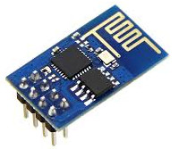
<ASIN:1871962676> <ASIN:B08XPRMK97> The micro:bit has a radio that has two modes, Bluetooth LE and ad-hoc point-to-point but it lacks WiFi connectivity. One solution is to use the low cost ESP8266 to make the connection via the micro:bit's serial port. As we will make a lot of use of the micro:bit's serial port it is assumed that you know roughly how it works. In particular, it is assumed that you are familiar with the material in the previous chapter. Before we get on to the details of using the ESP8266 we need to find out what makes it special. The Amazing ESP8266The ESP8266 is a very odd and amazing device. It is remarkably low cost, $5 or less, but it is a full microprocessor with GPIO lines, RAM and built in WiFi. It is built by a Chinese company Espressif Systems but there are a number of copies on the market. The proliferation of devices and software revisions makes it difficult to work with, but it is well worth the effort. The module used in this chapter is the ESP8266 ESP-01 which is widely available from many different sources but they all look alike:
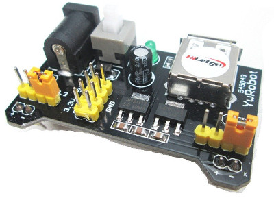
While you can set up a development system yourself and program the ESP8266 to do almost anything, it comes with built-in software that allows it to be used as a WiFi module for other processors. This is how we are going to use it to give the micro:bit a WiFi capability. The ESP8266 connects to the micro:bit using the serial port. The micro:bit controls it and transfers data using a system of AT commands. These were commonly used to control modems and other communication equipment and they still are used in mobile phone modems. A bigger problem is that there are new versions of the firmware and some of these might not work in exactly the same way. However, it should be easy to make the changes necessary. Connecting the ESP8266 ESP-01There a number of minor problems in using the device. The first is that it comes with an 8-pin male connector which is not prototype board-friendly. The best solution to this is to use some female-to male jumper cables to connect it to the prototype board, or use female-to-female cables to connect directly to the micro:bit breakout board. A second problem is caused by the fact that the device is powered from a 3.3V supply. This might tempt you to try to power it from the micro:bit's 3.3V supply. This will not work. The ESP8266 takes a lot of current, 300mA or so, when transmitting. The micro:bit cannot supply this much current. You need to use a separate 3.3V power supply. Of course, you can use this to power both the ESP8266 and the micro:bit and in some situations this would be an advantage. You can use one of the many low-cost prototyping board power supplies with no problems:
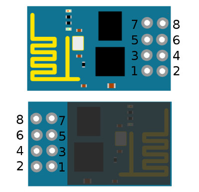
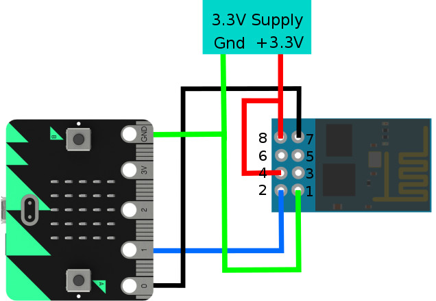
The pin functions are: 1 Ground connect to ground From the pinouts you should be able to work out the way the ESP8266 has to be connected to the micro:bit. If we use P0 as Tx from the micro:bit and P1 as Rx to the micro:bit we have to connect ESP-01 pin 7 to P0, pin 2 to P1 and ESP-01 pins 8 and 4 to the external power supply. To make it all work we also have to connect ESP-01 pin 1 to the ground of the external power supply ground and to the ground of the micro:bit, as shown:
|
||||||||
| Last Updated ( Tuesday, 12 July 2022 ) |