| Raspberry Pi CM5 IoT In C - Getting Started With PIO |
| Written by Harry Fairhead | |||||
| Wednesday, 04 June 2025 | |||||
Page 2 of 4
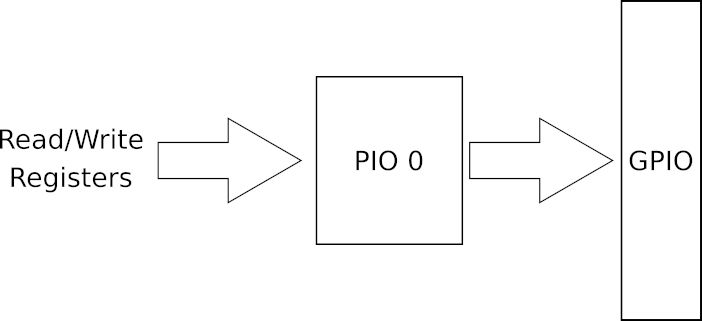
PIO Basic ConceptsThe problem with getting to grips with the PIO is that there are two distinct views of it – inside and outside. You can also add to this the extra complication of setting up a project that makes use of it, but that is a one-time problem. The best way to think about the PIO is as a black box that performs some transaction using GPIO lines and presents and accepts data from the processor – exactly like other I/O subsystems PWM, SPI, I2C etc. The only difference is that the transaction it performs is programmable.
This is the same situation as for the I2C or SPI hardware – once set up you communicate with the PIO by reading and writing registers and it is associated with a number of GPIO lines. Whereas the Pico has two PIO blocks, PIO 0 and PIO 1 the CM5 has a single PIO block, PIO 0. You communicate with the PIO by reading and writing registers, but, as with other hardware modules, the Pico SDK provides functions to do this for you on the Pico. The PIO driver for the CM5 implements the usual Linux file approach to drivers and it would be used directly via ioct calls – and these aren’t documented. The PIOlib library works as a wrapper and implements the Pico SDK by converting calls to it into ioct calls. This allows you to run Pico PIO programs on the CM5 with minimal changes. Configuring GPIO for PIO OutputThe first and most important thing to master is that the PIO doesn’t use instructions that work with particular GPIO lines. You don’t write a PIO program that sets the output of GPIO 2, say. Instead you specify which GPIO lines are to be included in a number of groups. The PIO has four different “state machines” that can be set to run a program stored in the PIO. Each state machine has its own set of GPIO lines that it works with and at the simplest each state machine can perform the same sort of task on different GPIO pins. So for example, if you programmed the PIO to be an SPI controller then you could define four different SPI interfaces, each to a different set of pins. It is also possible to run each state machine from a different program, but more of this later. Each state machine has two sets of output lines:
You can set the OUT group using: sm_config_set_out_pins (pio_sm_config *c, uint out_base,
uint out_count)
which modifies a configuration struct c which you use later to configure the state machine using pio_sm_init. The out_base parameter gives the first GPIO line in the group and the out_count parameter gives you the number of lines in the group. By default all of the OUT pins are set to high impedance mode and have to be explicitly set to act as outputs.
You can set the SET group using: sm_config_set_set_pins (pio_sm_config *c, uint set_base,
uint set_count)
which again modifies a configuration struct c which you use later to configure the state machine using pio_sm_init. The set_base parameter gives the first GPIO line in the group and the set_count parameter gives you the number of lines in the group. By default all of the SET pins are set to high impedance mode and have to be explicitly set to act as outputs. A third group of output lines, SIDESET, is also available and while it turns out to be very useful it is slightly more difficult to understand. We will return to it later. Notice that a PIO program doesn’t write to a particular GPIO line but to one of the groups of lines and these are defined by using the SDK functions in your C program. Also notice that the groups of GPIO lines are associated with different PIO instructions. The OUT group is used by the out instruction and the SET group is used by the set instruction. This might seem a complicated way to go about things but it allows you to write PIO programs that work with a general group of lines and then use a C program to determine which particular GPIO lines are used i.e. you can change which GPIO lines are used without changing the PIO program. PIO BlinkyNow it is time to write and run our first PIO program and in the grand tradition we will, eventually, write a Blinky program – the Hello World of hardware. The PIO is programmed using a special assembly language and we will return to its main features later, but for now you can most probably understand the meaning of our first simple program: .program squarewave This should be stored in sqwave.pio in the project folder that contains the C program that makes use of it. The first instruction set pindirs, 1 sets pin 1 in the SET group of pins to be an active output, i.e. it changes from a high impedance state to an output. This is more complicated than it seems. More of exactly how this works in the section on Output to the GPIO but essentially the value is used as a bit mask setting I/O lines to input or output e.g. 5 or 101 sets the first and third line in the SET group to output. The loop that follows this repeatedly changes the first pin in the SET group of pins from high to low. Again the value is a bit mask that is used to set the pins in the SET group. Notice that from this program you cannot tell which pins are actually being used – this is set in your C program via the PIO registers or the equivalent SDK functions. |
|||||
| Last Updated ( Wednesday, 04 June 2025 ) |