| Raspberry Pi IoT In C - 1-Wire Via Serial |
| Written by Harry Fairhead | ||||
| Monday, 28 December 2020 | ||||
Page 1 of 3 The serial port is capable of decoding more protocols than just R3232. For example you can use it to work with 1-Wire bus devices and it is easy and reliable. This is an extract from the newly-published Raspberry Pi IoT in C, Second Edition. Raspberry Pi And The IoT In C Second EditionBy Harry Fairhead
Buy from Amazon. Contents
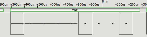
<ASIN:1871962633> <ASIN:B08KLNT2JC> The serial port is one of the oldest of ways of connecting devices together, but it is still very useful as it provides a reasonably fast communication channel that can be used over a larger distance than most other connections such as USB. Today, however, its most common and important use is in making connections with small computers and simple peripherals. It can also be used as a custom signal decoder as explained in this extract from a full chapter on using serial. Serial ProtocolThe serial protocol is very simple. It has to be because it was invented in the days when it was generated using electromechanical components, motors and the like. It was invented to make early teletype machines work and hence you will often find abbreviations such as TTY used in connection with it. As the electronic device used to work with serial is called a Universal Asynchronous Receiver/Transmitter, the term UART is also often used. The earliest standards are V24 and RS232. Notice, however, that early serial communications worked between plus and minus 24V and later ones ±12V. Today's serial communications work at logic, or TTL, levels of 0V to 5V or 0V to 3.3V. This voltage difference is a problem we will return to later. What matters is that, irrespective of the voltage, the protocol is always the same. For the moment let's concentrate on the protocol. As already mentioned, the protocol is simple. The line rests high and represents a 0. When the device starts to transmit it first pulls the line low to generate a start bit. The width of this start bit sets the transmission speed - all bits are the same width as the start bit. After the start bit there are a variable number, usually seven or eight, data bits, an optional single parity bit, and finally one or two 0 stop bits. Originally the purpose of the start bit was to allow the motors etc to get started and allow the receiving end to perform any timing corrections. The stop bits were similarly there to give time for the motors to come back to their rest position. In the early days the protocol was used at very slow speeds; 300 baud, i.e. roughly 300 bits per second, was considered fast enough. Today the protocol is much the same but there is little need for multiple stop bits and communications is often so reliable that parity bits are dispensed with. Transmission speeds are also higher - typically 9600 or 115200 baud. To specify what exact protocol is in use, you will often encounter a short form notation. For example, 9600 baud, 8 data bits, no parity, one stop bit, will be written as 9600 8n1. Here you can see the letter 0 (01101111 or 0x6F) transmitted using 8n1:
Notice that the signal is sent least significant bit first. The first low is the start bit, then the eight dots show the ideal sampling positions for the receiver. The basic decoding algorithm for receiving serial data is to detect the start of the start bit and then sample the line at the center of each bit time. Notice that the final high on the right is the stop bit. Notice also that the sampling points can be put to use on custom protocols. As long as the data is transmitted in fixed time “cells” indicated by a start bit you can use a serial port to read individual bits. For a serial connection to work, it is essential that the transmitter and the receiver are set to the same speed, data bits and parity. Serial interfaces most often fail because they are not working with the same settings. A logic analyzer with a serial decoder option is an essential piece of equipment if you are going to do anything complicated with serial interfacing. What is a baud? Baud rate refers to the basic bit time. That is, 300 baud has a start bit that is 1/300s wide. This means that for 9600 baud a bit is 1/9600 wide or roughly 104µs and at 115200 baud a bit is 1/115200 or roughly 8.6µs. Notice that baud rate doesn't equate to speed of sending data because there is an overhead in stop, start and perhaps parity bits to include in the calculation. In chapter but not in this extract.It is assumed that you know the basic functioning of the serial port.
|
||||
| Last Updated ( Monday, 28 December 2020 ) |