| The Pico In MicroPython: PWM |
| Written by Harry Fairhead & Mike James | ||||||||||||||||||||||||||||||||||||||||||||||||||||||||||||||||||||||||
| Monday, 26 July 2021 | ||||||||||||||||||||||||||||||||||||||||||||||||||||||||||||||||||||||||
Page 1 of 3 The Pico has a particularly flexible PWM generator but to get the most out of it you need to understand how it works. This is an extract from our latest book all about the Pico in MicroPython. Programming the Raspberry Pi Pico/W In MicroPython Third EditionBy Harry Fairhead & Mike James
Buy from Amazon. Contents
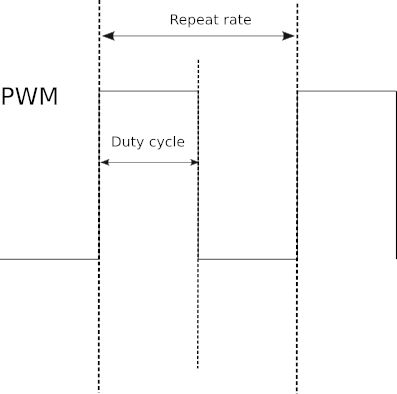
Also of interest: **** articles from the second edition not yet updated. <ASIN:B0BR8LWYMZ> <ASIN:B0BL1HS3QD> One way around the problem of getting a fast response from a microcontroller is to move the problem away from the processor. In the case of the Pico there are some built-in devices that can use GPIO lines to implement protocols without the CPU being involved. In this chapter we take a close look at the use of Pulse Width Modulation (PWM) including generating sound, driving LEDs and servos. When performing their most basic function, i.e. output, the GPIO lines can be set high or low by the processor. How fast they can be set high or low depends on the speed of the processor. Using the GPIO line in its Pulse Width Modulation (PWM) mode you can generate pulse trains up to 60MHz. The reason for the increase in speed is that the GPIO is connected to a pulse generator and, once set to generate pulses of a specific type, the pulse generator just gets on with it, without needing any intervention from the GPIO line or the processor. In fact, the pulse output will continue after your program has ended. Of course, even though the PWM line can generate pulses very fast pulses, usually what you want to do is change the nature of the pulses and this is a slower process involving the processor. Some Basic Pico PWM FactsThere are some facts worth getting clear right from the start, although some of their significance will only become clear as we progress. First, what is PWM? The simple answer is that a pulse width modulated signal has pulses that repeat at a fixed rate, say one pulse every millisecond, but the width of the pulse can be changed. There are two basic things to specify about the pulse train that is generated, its repetition rate and the width of each pulse. Usually the repetition rate is set as a simple repeat period and the width of each pulse is specified as a percentage of the repeat period, referred to as the duty cycle. So, for example, a 1ms repeat and a 50% duty cycle specifies a 1ms period, which is high for 50% of the time, i.e. a pulse width of 0.5ms. The two extremes are 100% duty cycle, i.e. the line is always high, and 0% duty cycle, i.e. the line is always low.
Notice it is the duty cycle that carries the information in PWM and not the frequency. What this means is that, in general, you select a repeat rate and stick to it and what you change as the program runs is the duty cycle. In many cases PWM is implemented using special PWM-generator hardware that is either built into the processor chip or provided by an external chip. The processor simply sets the repeat rate by writing to a register and then changing the duty cycle by writing to another register. This ideally provides the best sort of PWM with no load on the processor and glitch-free operation. You can even buy add-on boards that will provide additional channels of PWM without adding to the load on the processor. The alternative to dedicated PWM hardware is to implement it in software. You can work out how to do this quite easily. All you need is a timing loop to set the line high at the repetition rate and then set it low again according to the duty cycle. You can implement this using either interrupts or a polling loop and in more advanced ways, such as using a DMA (Direct Memory Access) channel. Pico PWMIn the case of the Pico, the PWM lines are implemented using special PWM hardware. It has eight PWM generators, each capable of two PWM outputs. Any of the GPIO lines can be used as PWM lines and this means you can have up to 16 PWM lines in operation at any given time. Things are a little more complicated in that each pair of outputs has the same frequency, which means you have eight, independently set, pairs of outputs. In addition, one of the outputs can be used as an input and this reduces the number of outputs available. The PWM generators are assigned to GPIO pins in a fixed order:
You don’t have to know about how the PWM hardware works, but it helps with understanding some of the restrictions. To create a PWM Pin object you have to pass its constructor a Pin object. For example: pwm16 = PWM(Pin(16)) creates a PWM object associated with GP16. You can set the frequency using: pwm16.freq(500) which sets the frequency in Hz. The PWM hardware isn’t enabled at this point. To start it generating a signal you have to set the duty cycle. This is done using: pwm16.duty_u16((duty) where duty is a value in the range 0 to 65,535 corresponding to 0 to 100%. There is also: pwm16.duty_ns(ns) which sets the time the line is high in nanoseconds. This isn’t as useful for general use and if you specify a time that is greater than the set period you will generate an exception. You can easily create your own duty cycle methods that work in terms of percentages or whatever way you want to specify the duty cycle. For example, you can create a new class which has a duty cycle set as a percentage: class myPWM(PWM):
def __init__(self, pin: Pin):
super().__init__(pin)
def duty(self,d):
print(65535*d//1000)
super().duty_u16(65535*d//1000)
In this case the percentage is specified multiplied by 10. For example, to set a 50% duty cycle you would use: pwm16 = myPWM(Pin(16)) pwm16.freq(250) pwm16.duty(500) Once you have set the duty cycle the PWM generator starts to output the specified PWM signal on the pin. Notice that this works even after your program has completed. To stop the PWM signal use: pwm16.deinit() You can change the frequency or duty cycle at any time. |
||||||||||||||||||||||||||||||||||||||||||||||||||||||||||||||||||||||||
| Last Updated ( Monday, 26 July 2021 ) |