| The Pico In MicroPython: PWM |
| Written by Harry Fairhead & Mike James | ||||
| Monday, 26 July 2021 | ||||
Page 2 of 3
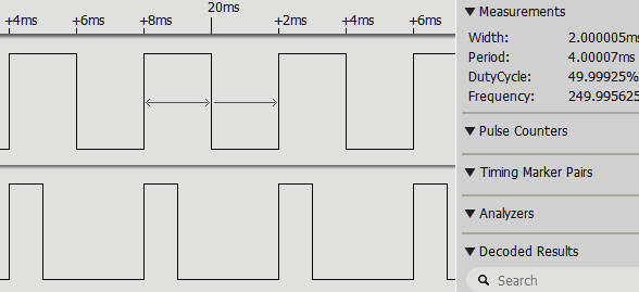
Although you don’t need to know anything about the PWM hardware, there is one limitation you need to be aware of. Each PWM generator supports two outputs which work at the same frequency and optionally different duty cycles. For example, if you look back to the table of PWM pin assignments you can see that PWM 0 has outputs on GP16 and GP17. This means that these two pins can only work at the same frequency. For example: from machine import Pin, PWM pwm16 = PWM(Pin(16)) pwm17 = PWM(Pin(17)) pwm16.freq(250) pwm16.duty_u16(65535//2) pwm17.duty_u16(65535//4) produces a PWM signal on GP16 and GP17 with the same frequency of 250Hz and duty cycles of 50% and 25% respectively. If you change the frequency on either pin, both change frequency. You can see the result in this logic analyzer display:
You can see from the logic analyzer trace that the pulses on each line start their duty cycle at exactly the same time. The PWM hardware can create phase-correct pulses where the pulses are aligned about their center point, but MicroPython doesn’t support this mode. However, it is fairly easy to write a function that sets or unsets phase-correct mode: def pwm_set_phase(sliceNo,phase):
Addr = 0x40050000 +0x14*sliceNo
if phase:
machine.mem32[Addr]=machine.mem32[Addr] | 0x2
else:
machine.mem32[Addr]=machine.mem32[Addr] & 0xFFFFFFFD
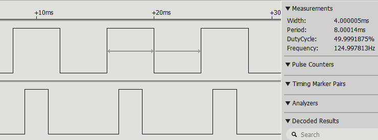
Using this we can generate phase-correct pulses: pwm16 = PWM(Pin(16)) pwm17 = PWM(Pin(17)) pwm16.freq(250) pwm_set_phase(0,True) pwm16.duty_u16(65535//2) pwm17.duty_u16(65535//4) Now you can see that the pulses don’t start at the same time, but they are centered around the same time:
As well as being able to set the level for each channel, you can also set the polarity. However, it is easy to write a function that will invert any channel: def pwm_set_polarity(sliceNo,channel,invert):
Addr = 0x40050000 +0x14*sliceNo
if invert:
machine.mem32[Addr]=machine.mem32[Addr] |
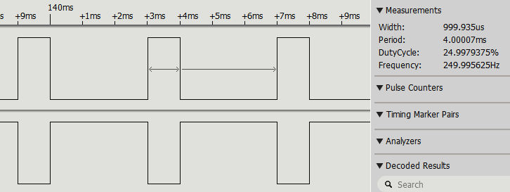
For example: pwm16 = PWM(Pin(16)) pwm17 = PWM(Pin(17)) pwm16.freq(250) pwm_set_polarity(0,1,True) pwm16.duty_u16(65535//4) pwm17.duty_u16(65535//4) and you can see that the output of channel B is inverted. Changing The Duty CycleFor reasons that will be discussed later, in most cases the whole point is to vary the duty cycle or the period of the pulse train. This means that the next question is, how fast can you change the characteristics of a PWM line? In other words, how fast can you change the duty cycle? There is no easy way to give an exact answer and, in most applications, an exact answer isn't of much value. The reason is that for a PWM signal to convey information it generally has to deliver a number of complete cycles with a given duty cycle. This is because of the way pulses are often averaged in applications. We also have another problem – synchronization. This is more subtle than it first seems. The hardware won't change the duty cycle until the current pulse is complete. You might think that the following program works to switch between two duty cycles on a per pulse basis: pwm16 = PWM(Pin(16))
pwm16.freq(50)
pwm16.duty_u16(65535//2)
while True:
pwm16.duty_u16(65535//2)
pwm16.duty_u16(65535//4)
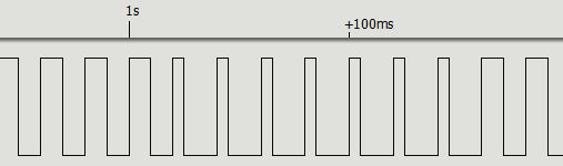
but if you try this out the result isn’t what you might expect on a first analysis:
You don’t get one 25% followed by one 50% pulse, but a varying number of each in turn. The reason is, of course, that the duty cycle is being set asynchronously.
|
||||
| Last Updated ( Monday, 26 July 2021 ) |