| The Pico In C: Basic PWM |
| Written by Harry Fairhead | ||||||||||||||||||||||||||||||||||||||||||||||||||||||||||||||||||||||||
| Monday, 06 September 2021 | ||||||||||||||||||||||||||||||||||||||||||||||||||||||||||||||||||||||||
Page 2 of 3
Pico PWM InitializationIn the case of the Pico, the PWM lines are implemented using special PWM hardware. It has eight PWM generators, each capable of two PWM outputs. Any of the GPIO lines can be used as PWM lines and this means you can have up to 16 PWM lines in operation at any given time. Things are a little more complicated in that each pair of outputs has the same frequency which means you have eight, independently set, pairs of outputs. In addition, one of the outputs can be used as an input and this reduces the number of outputs available. The PWM generators are assigned to GPIO pins in a fixed order:
You don’t have to know about how the PWM hardware works, but it helps with understanding some of the restrictions. To make use of the PWM hardware you need to change the libraries statement in CMakeLists.txt to: target_link_libraries(myprogram pico_stdlib
hardware_gpio hardware_pwm)
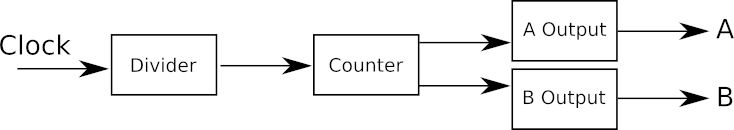
that is you you need to add hardware_pwm to the libraries. You also need to add: #include "hardware/pwm.h" to the start of your program. Many of the programs that follow are variations on the main program and hence only the main program is presented. If you want a listing of the full program then visit this book’s web page at www.iopress.info. When you enable PWM functions on a GPIO line: gpio_set_function(gpio, GPIO_FUNC_PWM); the PWM generator “slice” that you get is as shown in the table. Which slice and channel you are working with is important because you have to specify this to configure the hardware. You could just look at the table and work out that when you use a particular GPIO line you have to use a particular slice. For example, if you use GP22 then you are working with 3A, which is the A output of the third slice. That is, the slice number is 3 and the channel number is 0. Alternatively you can use the functions: static uint pwm_gpio_to_slice_num (uint gpio) static uint pwm_gpio_to_channel (uint gpio) to return the slice and channel number for the PWM hardware connected to the specified pin. For example: gpio_set_function(22, GPIO_FUNC_PWM); slice=pwm_gpio_to_slice_num (22); channel=pwm_gpio_to_channel (22); returns slice 3 and channel 0. Once you have set the pin function and set up the PWM you can start and stop it generating a signal using: pwm_set_enabled (uint slice_num, bool enabled) There are times when you need to turn multiple PWM signals on or off and for this you can use: pwm_set_mask_enabled (uint32_t mask) The mask represents the eight PWM slices as the first eight bits. You also need to modify the target_link_libraries instruction in the CMakeLists.txt file to read: target_link_libraries(blinky pico_stdlib hardware_pwm) PWM ConfigurationYou can see a simplified model of the PWM generator below. This isn’t the full story, but it is how best to think of things when you are just getting started or when you are generating simple PWM signals:
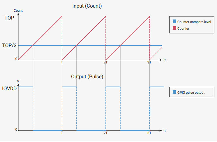
The way that the 16-bit counter works is the key to understanding PWM generation. The default clock is 125MHz and the divider is initialized to 1, which means the counter is stepped on every 8ns. You can modify the counter’s behavior by setting a wrap value: pwm_set_wrap (uint slice_num, uint16_t wrap) This is the highest value the counter will count up to before either rolling over to zero or starting to count down to zero. These two different behaviors are controlled by enabling or disabling the “phase-correct” mode, the reason for the name will be explained later: pwm_set_phase_correct (uint slice_num, Phase correction disabled results in the counter counting up to the wrap value and then resetting to zero. Phase correction enabled makes the counter count up to the wrap value and then down to zero. The PWM signal is generated from the counter value by setting the channel’s level: pwm_set_chan_level (uint slice_num, uint chan, or for both channels at the same time: pwm_set_both_levels (uint slice_num, uint16_t level_a, There is also the helper function: pwm_set_gpio_level (uint gpio, uint16_t level) which will set the level of the specified GPIO line without being told the slice or channel. Each time the counter exceeds the level, the state of the output line changes. The line is set high when the count starts and is set low when the level is exceeded. The count continues and the line is set high again when it restarts. You can see this in action in non-phase-correct mode in the diagram below (taken from the documentation):
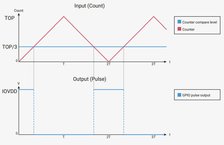
In phase-correct mode we have a similar diagram:
You can see that the counter wrap value sets the frequency and the level sets the duty cycle. It is also obvious that the frequency is halved in phase-correct mode. You can now also see the reason it is called phase-correct mode. In the non-phase-correct mode, as you change the duty cycle the start of the pulse stays fixed, but the center of the pulse moves. In phase-correct mode the start and end of the pulse move, but the center of the pulse stays fixed – its phase is unchanged. There are applications where this difference matters, but for most PWM situations you can ignore the difference. Another subtle point is that you can change the level at any time but the change only takes effect when the counter resets, so you can’t accidentally get two pulses during one count cycle. As already stated, the wrap value determines the frequency. It doesn’t take too much algebra to work out that in non-phase-correct mode: f = fc /(wrap+1) where fc is the frequency of the clock after any division has been taken into account. More usefully you can work out the wrap needed to give any PWM frequency: wrap = fc/f - 1 Similarly, the level sets the duty cycle: level = wrap * duty where duty is the duty cycle as a fraction. For example, with a clock frequency of 125MHz in non-phase-correct mode you can generate a PWM signal of 10kHz using a wrap of 12,500 and a 25% duty cycle implies a level of 3,125. In phase-correct mode the formulas have to be adjusted to take into account counting both up and down, which halves the frequency: f = fc /2(wrap+1) wrap = fc/2f - 1 level = wrap * duty |
||||||||||||||||||||||||||||||||||||||||||||||||||||||||||||||||||||||||
| Last Updated ( Sunday, 19 May 2024 ) |