| The Pico In C: Basic PWM |
| Written by Harry Fairhead | |||||||
| Monday, 06 September 2021 | |||||||
Page 3 of 3
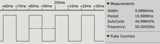
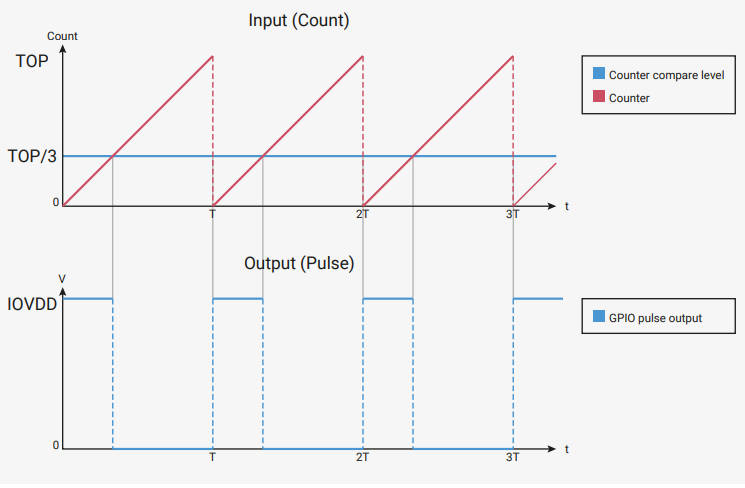
Clock DivisionThe PWM counter is 16 bits and this means that once you reach a wrap of 65,534 you cannot decrease the frequency. Given a clock input of 125MHz this puts the lowest PWM frequency at 1.9kHz. This isn’t much good if you need a 50Hz signal to drive a servo, see later. The solution is to use the clock divider to reduce the 125MHz clock to something lower. The clock divider is a 16-bit fractional divider with eight bits for the integer part and four bits for the fraction. You can set the clock using: pwm_set_clkdiv_int_frac (uint slice_num, and if you want to specify the divider as a floating point value you can use: pwm_set_clkdiv (uint slice_num, float divider) The divider is decomposed into an 8-bit integer and a 4-bit fractional part, which specifies the fraction as fract/16. This means that the largest divisor is 255 15/16 which which gives the lowest clock frequency as: 522,875.81Hz You can use the formulas listed above to work out the wrap and level as long as fc is the resulting clock after division. For example, if you set a clock divider of 2 with a clock frequency of 125MHz in non-phase-correct mode you can generate a PWM signal of 5kHz using a wrap of 12,500 and a 50% duty cycle implies a level of 6,250. This is simple enough, but notice that you now usually have more than one way to generate any particular PWM frequency – how should you choose a clock divider? The answer is to do with the resolution of the duty cycle you can set. For example, suppose you select a divider that means that to get the frequency you want you have to use a wrap of 2. Then the only duty cycles you can set are 0, 1/3, 2/3 or 100%, corresponding to levels of 0, 1, 2 and 3. If you want to set more duty cycles then clearly you need to keep wrap as big as possible. In fact, it is easy to see that the resolution in bits of the duty cycle is given by log2 wrap and, as the maximum value of wrap is 65,535, obviously the maximum resolution is 16 bits, i.e. the size of the counter. Putting all this together you can see that you should always choose a divider that lets you use the largest value of wrap to generate the frequency you are looking for. In other words, the divider should be chosen to be bigger than the frequency you need, but as close as possible. In other words: divider = Ceil(16fc/65536fpwm)/16 divider = Ceil(fc/4096fpwm)/16 Where fc is the clock frequency, fpwm is the required frequency and Ceil is the ceiling function which returns the integer just bigger than its argument. For example, if we want a PWM signal at 50Hz the calculation is: divider = Ceil(125000000/(4096*50))/16 = 611/16 = 38.1875 If you are setting the divider using the integer and 4-bit fractional part then it is the 611 value that is useful as its bottom four bits 0011 gives the fractional part. So the clock divider is set using: pwm_set_clkdiv_int_frac (slice_num, 38,3); Using this divisor gives the effective clock frequency of: Using this we can now compute the wrap needed: If you try this out you will discover that: pwm_set_clkdiv_int_frac (slice_num, 38,3); pwm_set_wrap(slice_num,65465); pwm_set_chan_level(slice_num, PWM_CHAN_A, 65465/2); produces a PWM wave form with a frequency of 50Hz:
A Frequency and Duty Cycle FunctionIn most cases you simply want to set a PWM frequency and duty cycle – you don’t want to have to calculate the best clock, wrap and level for the task, but sometimes this is necessary. In most cases you can do the job automatically with a function which makes use of the formulas listed above: uint32_t pwm_set_freq_duty(uint slice_num, This works by first working out the divider before division by 16, i.e. divider16. Notice that: + (clock % (f * 4096) != 0) is a standard way of rounding up positive values as it adds one if there is a remainder. The if statement checks to see if the divider is less than one and if it is we set divide16 to its minimum value. Next, we compute the wrap needed to achieve the specified frequency using that divider. Finally, we use the pwm functions to set the clock divider, wrap and level. The value of wrap is returned so that the calling program can check that the duty cycle is being set with sufficient resolution. For example, to set a PWM signal at 50Hz with a 75% duty cycle: pwm_set_freq_duty(slice_num,chan, 50, 75); A full main program using the function is (remember to add hardware_pwm to the CMakeLists.txt file): #include "pico/stdlib.h"
#include "hardware/pwm.h"
int main(){
gpio_set_function(22, GPIO_FUNC_PWM);
In Chapter but not in this extract
Summary
Programming the Raspberry Pi Pico In C
|

Kaggle Contest To Predict 3D Structure Of RNA 09/01/2026 A contest with a first prize of $50,000 launched on January 7, 2026. It is the second part of the Stanford RNA 3D Folding challenge and has already 102 teams actively participating. |
Atlas Production Ready This Year 18/01/2026 The latest incarnation of Boston Dynamics' Atlas Robot took to the stage at CES 2026. Hyundai announced that it plans to deploy tens of thousands of the humanoid robot in its own manufacturi [ ... ] |
More News
|

Comments
or email your comment to: comments@i-programmer.info