|
Page 1 of 4 PWM is a basic output mode suitable for controlling servos, motors and more. Linux has a driver that means that you can use PWM without worrying about the hardware - if you know how.
This content comes from our newly published book:
Raspberry Pi IoT In PythonUsing Linux Drivers
Second Edition
By Harry Fairhead & Mike James

Buy from Amazon.
Contents
- Choosing A Pi For IoT
- Getting Started With Python
- Drivers: A First Program
- The GPIO Character Driver
- GPIO Using Ioct ***NEW!!
-
GPIO Events
-
-
Some Electronics
-
Pulse Width Modulation Extract: PWM *
-
SPI Devices
-
I2C Basics Extract: I2C *
-
The I2C Linux Driver
-
Advanced I2C
-
Sensor Drivers
-
-
Going Further With Drivers
-
Appendix I
*From the first edition waiting for update.
<ASIN:B0CT46R6LF>
One way around the problem of getting a fast response from a microcontroller is to move the problem away from the processor. In the case of the Pi's processor there are some built-in devices that can use GPIO lines to implement protocols without the CPU being involved. In this chapter we take a close look at pulse width modulation (PWM) including generating sound and driving LEDs.
When performing their most basic function, i.e. output, the GPIO lines can be set high or low by the processor. How quickly they can be set high or low depends on the speed of the processor.
Using the GPIO line in its Pulse Width Modulation (PWM) mode you can generate pulse trains up to 4.8MHz, i.e. pulses just a little more than 0.08µs. The reason for the increase in speed, a factor of at least 100, is that the GPIO is connected to a pulse generator and, once set to generate pulses of a specific type, the pulse generator just gets on with it without needing any intervention from the GPIO line or the processor. In fact, the pulse output can continue after your program has ended if you forget to reset it.
Of course, even though the PWM line can generate pulses as short as 0.1µs, it can only change the pulses it produces each time that the processor can modify them. For example, you can't use PWM to produce a single 0.1µs pulse because you can't disable the PWM generator in just 0.1µs. This said, hardware generated PWM is available on the Pi and there is a good PWM driver that makes it very easy to use.
Some Basic Pi PWM Facts
There are some facts worth getting clear right from the start, although their full significance will only become clear as we progress.
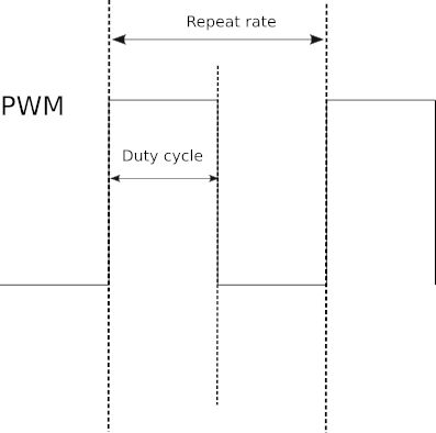
First what is PWM? The simple answer is that a Pulse Width Modulated signal has pulses that repeat at a fixed rate, say, one pulse every millisecond, but the width of the pulse can be changed.
There are two basic things to specify about the pulse train that is generated, its repetition rate and the width
of each pulse. Usually the repetition rate is set as a simple repeat period and the width of each pulse is specified as a percentage of the repeat period, referred to as the duty cycle. So, for example, a 1ms repeat and a 50% duty cycle specifies a 1ms period, which is high for 50% of the time, i.e. a pulse width of 0.5ms.
The two extremes are 100% duty cycle, i.e. the line is always high, and 0% duty cycle, i.e. the line is always low. The duty cycle is simply the proportion of time the line is set high. Notice it is the duty cycle that carries the information in PWM and not the frequency. What this means is that, generally, you select a repeat rate and stick to it and what you change as the program runs is the duty cycle.
There are many ways to specify a PWM signal – frequency and duty cycle, time high and time low and so on. It is easy to convert between these different representations.
As you can guess, there are no PWM inputs, just output. If for some reason you need to decode, or respond to, a PWM input then you need to program it using the GPIO input lines and the pulse measuring techniques introduced in previous chapters.
Software PWM
The alternative to dedicated PWM hardware is to implement it in software. You can quite easily work out how to do this. All you need is to set a timing loop to set the line high at the repetition rate and then set it low again according to the duty cycle. You can easily implement software PWM using the GPIO character driver:
import gpiod
from time import sleep
chip = gpiod.Chip("0")
line = chip.get_line(4)
line.request(consumer="myprog.py",
       type=gpiod.LINE_REQ_DIR_OUT, default_vals=[0])
period = 20
duty = 25
ontime = period/1000 * duty/ 100
offtime = period/1000 - ontime
while(True):
    line.set_value(1)
    sleep(ontime)
    line.set_value(0)
    sleep(offtime)
The basic idea is to take the period in ms and the duty cycle as a percentage and work out the on and off time.
A more advanced version of the same program makes use of a thread to implement the toggling of the PWM line. To understand how this works you need to be happy with threads:
import gpiod
from time import sleep
import threading
def softPWM(line,period,duty):
    ontime = period/1000 * duty/ 100
    offtime = period/1000 - ontime
    while(True):
        line.set_value(1)
        sleep(ontime)
        line.set_value(0)
        sleep(offtime)
chip = gpiod.Chip("0")
line = chip.get_line(4)
line.request(consumer="myprog.py",
         type=gpiod.LINE_REQ_DIR_OUT, default_vals=[0])
period = 20
duty = 75
IntThread=threading.Thread(target=softPWM,
                              args=(line,period,duty))
IntThread.start()
while(True):
    print("working",flush=True)
    sleep(2)
This will generate the PWM signal on the specified gpio line independent of the main program. If you want to use this in production you would need to add error handling and some functions to pause and stop the thread.
The accuracy of the PWM signal goes down as the frequency increases. At a period of 20ms and a duty cycle of 25% the frequency and duty cycle are typically 48.5Hz and 25.5% i.e. around 2% accuracy but at 2ms the figures are 425Hz and 29% i.e. around 10% accuracy. It becomes increasingly inaccurate and becomes unusable at around 1kHz. The reason is that sleep is used for the timing. This suspends the thread and relies on the operating system to restart it. The problem is that as the requested sleep time becomes shorter the operating system fails to restart the thread early enough due to it running other threads while the PWM thread is suspended. You could replace the sleep call by a busy wait loop to make the timing more accurate but this wouldn’t allow the operating system to run another thread while waiting. This would work well on a multicore Pi 4 but would be not so good on a single core Pi Zero.
Software implemented PWM isn’t workable for higher frequencies. It is, however, good enough to work at 50Hz, which is suitable for driving servos – see later.
|