| Raspberry Pi IoT In C - Basic Pulse Width Modulation |
| Written by Harry Fairhead | |||||
| Monday, 20 June 2022 | |||||
Page 2 of 4
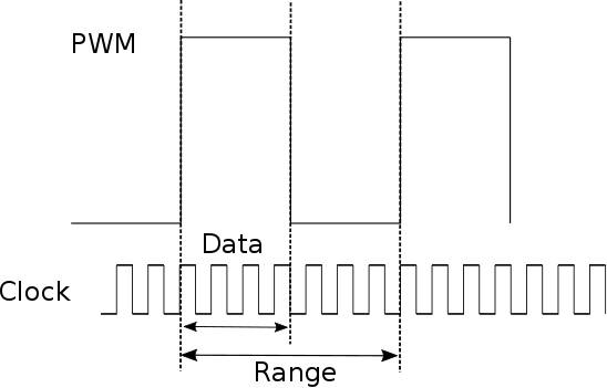
PWM ModesThe PWM hardware is more sophisticated than you might have encountered before. The first big difference is that it can work in two modes, mark/space or balanced. In fact there are even more options, but these are the only two that have a common use. The PWM signal is generated using two counters, range and data. The range counter counts down at the current clock rate and PWM generation starts over when it reaches zero. In mark/space mode the data counter starts counting down at the same time as the range counter and when it reaches zero the output is inverted. In other words, range gives the repeat rate and data sets the duty cycle, both in terms of the underlying clock rate:
In mark/space mode you set the duty cycle as the ratio of data to range and the line stays high for Data clock pulses. This is fine for many common PWM devices such as a servo motor, but for applications that only need the power transfer provided by PWM it isn't so good. The reason is that, despite the clock frequency being high, the actual PWM frequency is much lower. Instead of holding the line high for one continuous time period, an alternative is to distribute the time that it is high across the entire period - this is balanced mode. Its advantage is that you get the same duty cycle spread out across the entire range period. For example, suppose you want a 1kHz pulse train with a 50% duty cycle to deliver half power or voltage to a device. The mark/space way of doing this switches the GPIO line on for 500µs and off for 500µs. The fluctuations in voltage are very slow and this causes problems for the driven device. A better way would be to divide the time into, say, 1µs blocks and spread the on and off times throughout the block. In this case the device would be high for 1µs and low for 1µs and the filtering problems would be much easier to solve. The algorithm for achieving the distribution of the "high" time across the full range period is given in the ARM manual as: context = 0;
for(i=0;i<range;i++) {
context = context + data;
if(context >= range){
context = context - range;
set line high
}else{
set line low
}
Suppose range is 8 and data is 4, giving a 50% duty cycle, then the algorithm generates: clock 1 2 3 4 5 6 7 8 context 4 8 4 8 4 8 4 8 line 0 1 0 1 0 1 0 1 mark/space mode 1 1 1 1 0 0 0 0 It is clear that range sets the repeat rate and data sets the duty cycle in both modes. Obviously using this way of specifying repeat rate and duty cycle means that you can select more than one range and data value for any given duty cycle, only the ratio of the two matters. For example, a range of 4 and data of 2 is also a 50% duty cycle. So how do you choose a suitable pair of values? The range gives you the possible number of duty cycle steps you can use. For example, for a range of 2 you modify the duty cycle to 0%, 50% or 100% by setting data to 0, 1 or 2. A range of 512 gives you 512 steps and is usually called 8-bit PWM and a range of 1024 gives you 1024 duty cycle steps and is usually called 16-bit PWM. To summarize:
You can now see why the clock frequency being supplied to the two PWM units doesn't constrain them to the same repeat rate. They can work at different rates as long as they can tolerate different duty cycle resolutions and hence range values. PWM FunctionsThe bcm2835 library provides PWM in an easy-to-use form. Its functions allow you to set the parameters of both PWM channels numbered 0 and 1. The fundamental frequency of the PWM is set by: void bcm2835_pwm_set_clock (uint32_t divisor) You can't set the clock speed directly. Instead you have to specify a divisor to reduce the 19.2MHz clock to a lower rate. The library provides some standard settings: BCM2835_PWM_CLOCK_DIVIDER_2048 9.375kHz BCM2835_PWM_CLOCK_DIVIDER_1024 18.75kHz BCM2835_PWM_CLOCK_DIVIDER_512 37.5kHz BCM2835_PWM_CLOCK_DIVIDER_256 75.0kHz BCM2835_PWM_CLOCK_DIVIDER_128 150.0kHz BCM2835_PWM_CLOCK_DIVIDER_64 300.0kHz BCM2835_PWM_CLOCK_DIVIDER_32 600.0kHz BCM2835_PWM_CLOCK_DIVIDER_16 1.2MHz BCM2835_PWM_CLOCK_DIVIDER_8 2.4MHz BCM2835_PWM_CLOCK_DIVIDER_4 4.8MHz BCM2835_PWM_CLOCK_DIVIDER_2 9.6MHz BCM2835_PWM_CLOCK_DIVIDER_1 4.6875kHz The largest divider you can specify is 0xFFF, or 4096, which gives the same frequency as specifying 1, i.e. 4.6875kHz. An important point to remember is that the clock rate is not the PWM repeat rate.
How the PWM pulses are created depends on the selected mode: void bcm2835_pwm_set_mode (uint8_t channel,
uint8_t markspace, uint8_t enabled)
channel has to be 0 or 1, markspace is 1 for mark/space mode and 0 for balanced and enabled is 1 to start the PWM pulses running. Finally you can set range using: void bcm2835_pwm_set_range (uint8_t channel, and you can set data using: void bcm2835_pwm_set_data (uint8_t channel, The largest value of range that seems to work in practice is 0xFF FFFF, over 268 million clock pulses, which at the highest clock rate is around 30s per repeat. |
|||||
| Last Updated ( Saturday, 25 June 2022 ) |