| Raspberry Pi IoT In C - Basic Pulse Width Modulation |
| Written by Harry Fairhead | ||||||||
| Monday, 20 June 2022 | ||||||||
Page 4 of 4
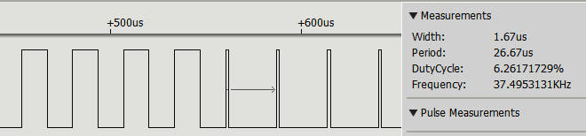
How Fast Can You Modulate?In most cases the whole point is to vary the duty cycle or the period of the pulse train, for reasons that will be discussed later. This means that the next question is how fast can you change the characteristic of a PWM line? In other words, how fast can you change the duty cycle? There is no easy way to give an exact answer and, in most applications, an exact answer isn't of much value. The reason is that for a PWM signal to convey information it generally has to deliver a number of complete cycles with a given duty cycle. This is because of the way pulses are often averaged in applications. We also have another problem – synchronization. There is no way to swap from one duty cycle to another exactly when a complete duty cycle has just finished. All you can do is use a timer to estimate when the pulse is high or low. What this means is that there is going to be a glitch when you switch from one duty cycle to another. Of course, this glitch becomes less important as you slow the rate of duty cycle change and exactly what is usable depends on the application. For example, set up the PWM to clock(2), 9.6MHz, which with range 256 gives a repeat time of 26.66µs. We can change the duty cycle from 0 to 256 and in this case we choose 128, i.e. 50%, and, 16, i.e. 6.25%, and switch between then after eight cycles: #include <stdio.h>
#include <stdlib.h>
#include <bcm2835.h>
int main(int argc, char** argv) {
if (!bcm2835_init())
return 1;
bcm2835_gpio_fsel(18, BCM2835_GPIO_FSEL_ALT5);
bcm2835_pwm_set_clock(2);
bcm2835_pwm_set_mode(0, 1, 1);
bcm2835_pwm_set_range(0, 256);
for (;;) {
bcm2835_pwm_set_data(0, 16);
bcm2835_delayMicroseconds((int)26.666*8);
bcm2835_pwm_set_data(0, 128);
bcm2835_delayMicroseconds((int)26.666*8);
}
return (EXIT_SUCCESS);
}
The result looks fairly good and notice that the change in duty cycle is correct, the last 50% unit is followed by a 6.25% unit:
The fastest PWM repetition rate that you can use is 26.6µs for an 8-bit resolution and you can change the duty cycle as frequently as once per pulse. In Chapter but not in this extract
Summary
Raspberry Pi And The IoT In C Second EditionBy Harry Fairhead
Buy from Amazon. Contents
<ASIN:1871962633> <ASIN:B08KLNT2JC> To be informed about new articles on I Programmer, sign up for our weekly newsletter, subscribe to the RSS feed and follow us on Twitter, Facebook or Linkedin. 
Comments
or email your comment to: comments@i-programmer.info
|
||||||||
| Last Updated ( Saturday, 25 June 2022 ) |