| Exploring Edison - The DS18B20 1-Wire Temperature Sensor |
| Written by Harry Fairhead | |||||
| Monday, 07 March 2016 | |||||
Page 2 of 4
InitializationEvery transaction with the a 1-wire device starts with an initialization handshake. First we have to get the GPIO lines set up correctly
This simply sets mraa line 32 to input and 31 to output. We also set a realtime priority to the entire program. This isn't really necessary as only the bit read/write functions are actually time critical as will be explained later. Also notice that the variable pinIn and pinOut have been made file level i.e. global so that they don't have to be passed to the functions that make use of them. In practice you can refactor this code to make them parameters if you want to create a more general 1-wire library. We also need the output line to be set to open collector. You cannot do this using mraa but it is easy enough to do via SYSFS as explained in Chapter 15. You have two choices to use the internal 2K pullup resistor or use an external resistor – in this example we use an external resistor. Using the functions given in Chapter 15 we can set the output line to open collector no pullup resistor using:
Notice that GPIO-44 corresponds to mraa pin 31. If you don't include these two function calls the bidirectional bus will not work. For completeness the putSetting function is:
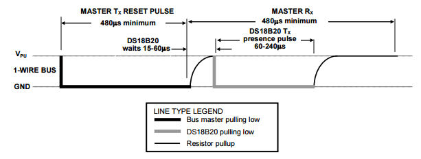
Now we have to send the initilaization pulse. This is simply a low pulse that lasts at least 480 microseconds, a 15 to 60 microsecond pause follows and then any and all of the devices on the bus pull the lin low for 60 to 240 microseconds.
This is fairly easy to implemnent as a function:
We pull the line low for 500 microseconds and then let it be pulled back up. After a 60 microsecond wait which is right at the start of the guaranteed period when the line should be low if there is an active device on the bus we read the input line and then wait another 500 microseconds to complete the data slot. As this is such a slow and inaccurate transaction it makes sense to use usleep rather than a busy wait loop. It releases control back to the OS so that some other program can run but it usually creates a pause that is longer than the time specified. Hence if there is a device the function should return zero and if there are no devices it should return a one.
If you try this partial program and have a logic analyser you will see something like:
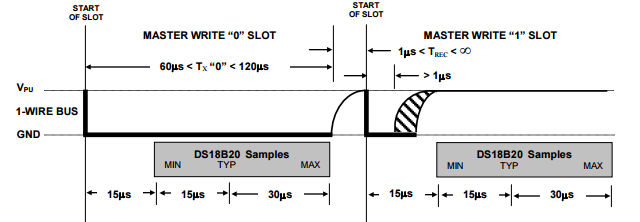
The actual initialization pulse is 567 microseconds and after a pause of 30 microsecond the device pulls the bus low for 110 microseconds in response - these timings can vary but a little over 90 microseconds after the end of the initialization pulse should always be within the presence pulse. Seeing a presence pulse is the simplest and quickest way to be sure that your hardware is working. Writing BitsOur next task is to implement the sending of some data bits to the device. The 1-wire bus has a very simple data protocol. All bits are sent using a minimum of 60 microseconds for a read/write slot. Each slot must be separated from the next by a minimum of 1 microsecond. The good news is that timing is only critical within each slot. You can send the first bit in a time slot and then take your time before you send the next bit - the device will wait for you. This means you only have to worry about timing withing the functions that read and write individual bits. To send a zero you have to hold the line low for most of the slot. To send a one you have to hold the line low for just between 1 and 15 microseconds and leave the line high for the rest of the slot. The exact timings can be seen below;
It seems reasonable to use the typical timings shown on the diagram. So for a zero we hold the line low for 60 microsecond then let it go high for the remainder of the slot. To send a one we hold the line for a bit more than 1 microsecond and then let it go high for the remainder of the slot. So our sendZero function is:
and our sendOne function is:
Notice that the functions keep control after letting the line go high again. In principle they could return and let the main program do some processing but this would mean that the main program had to hold off sending another bit until the 60 microseconds was up. This approach isn't efficient but it is simple. Also notice that as the time periods are short and they have to be fairly repeatable a busy wait is the best option for the delay. With these constants the measured pulse widths are for a zero the the line is held low for just over 60 microseconds with a pause of about 1.5 microseconds and for a one the line is held low for 1.5 microseconds and the slot is about 60 microseconds in total. As the only time critical operations are the actual setting of the line low and then back to high there is no need to worry too much about speed of operation of the entire function so we might as well combine the two functions into a single writeBit function:
The code at the start of the function simply increases the time between slots slightly. You can see a one followed by a zero in the following logic analyzer trace:
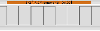
A First CommandAfter discovering that there is at least one device connected to the bus the master has to issue a ROM command. In many cases the ROM command used first will be the Search ROM command which enumerates the 64-bit codes of all of the devices on the bus. After collecting all of these codes the master can used the Match ROM commands with a specific 64-bit code to select the device the master wants to talk to. While it is perfectly possible to implement the Search ROM procedure it is simpler to work with the single device by using commands which ignore the 64-bit code and address all of the devices on the bus at the same time. Of course this only works as long as there is only one device on the bus. If there is only one device then we can use the Skip ROM command 0xCC to tell all the devices on the bus to be active. As we have a writeBit function this is easy:
Notice that 0xCC is 1100 1100 in binary and the 1-wire bus sends the least significant bit first. If you try this out you should find it works but device doesn't respond because it is waiting for another command. Again as the time between writing bits isn't critical we can take this first implementation of the function and write something more general if slightly slower. The writeByte function will write the low 8 bits of an int to the device:
Using this we can send a Skip ROM command using:
You can see the pattern of bits sent by the Edison on a logic analyzer:
|
|||||
| Last Updated ( Wednesday, 11 May 2016 ) |