| Exploring Edison - The DS18B20 1-Wire Temperature Sensor |
| Written by Harry Fairhead | |||||
| Monday, 07 March 2016 | |||||
Page 3 of 4
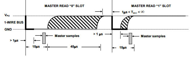
Reading BitsWe already know how the master sends a one and a zero the protocol for the device is exactly the same except that the master still provides the slots starting pulse. That is the master starts a 60 microsecond slot by pulling the bus down for a bit more than 1 microsecond. Then the device either holds the line down for a further 15 microseconds minimum or it simply allows the line to float high. See below for the exact timings:
So all we have to do to read bits is to pull the line down for just a bit more than 1 microsecond and then sample the bus at the end of a 15 microsecond pause.
The readBit function pulls the line low for about 1.5 microsecond and measures the line state at around 12.5 microseconds. The total slot time is around 630 microseconds. Again it is better to use busy waits as the time periods are short and need to be repeatable. A logic analyzer shows the typical pattern of bits from the device:
The narrow initial low pulse corresponding to a one slot is 1.5 microseconds and the longer low pulses corresponding to a zero slot is 28 microseconds with the slot lasting 690 microseconds. After using the program for a lot of measurements it turns out the a loop time of 450 iterations reduces the error rate considerably. It seems earlier is better. Initiating A Temperature ConversionOur next task is to send a Convert command 0x44. This starts the DS18B20 making a temperature measurement. Depending on the resolution selected this can take as long as 750ms. How the device tells the master that the measurement has completed depends on the mode it is operating in but using an external power line, i.e. not using parasitic mode, the device sends a zero bit in response to a bit read until it is completed when it sends a 1. As we already have a readBit function this is easy. The software polls for the completion by reading the bus until it gets a 1 bit:
You can of course test the return value to check that the result has been obtained. When the function returns the new temperature measurement is stored in the devices scratchpad memory and now all we have to do is read this. Reading The ScratchpadThe scratchpad memory has nine bytes of storage in total and does things like control the accuracy of conversion and provide status information. However in our simple example the only two bytes of any great interest are the first two - which hold the result of a temperature conversion. Before we move on to read the scratchpad we need a function that will read a byte. As in the case of writing a byte there is no time criticality in the time between reading bits so we don't need to take extra special care in constructing the function;
The only difficult part is to remember that the 1-wire bus sends the least significant bit first and so this has to be shifted into the result from the right. Now we have a readByte function getting the data is simple. We have to issue a Read Scratchpad 0xBE command and then read the nine bytes that the device returns. However, to send the new command we have to issue a new initialization pulse and a Skip ROM 0xCC command followed by a read scratchpad command 0xBE:
Now the data is ready to read. We can read all nine bytes of it or just the first two. The device will keep track of where the read is so if you come back later and read more bytes you will get the first one not read. If you issue an initialization pulse then the device aborts the data transmission. We only need the first two bytes which are the least and most significant bytes of the 11-bit temperature reading as a 16-bit, 2-complement integer.
Getting the TemperatureAll we now have to do do is to put the two bytes together as a 16-bit integer. As the Edison supports a 16-bit int we can do this very easily:
Notice that this only works because int16_t really is a 16-bit integer. If you were to use:
Then temp1 would be correct for positive temperatures but it would give the wrong answer for negative values because the sign bit isn't propagated into the top 16 bits. If you want to use a 32-bit integer then you will have to propagate the sign bit manually:
Now we have a basic program to read the temperature and some useful 1-wire functions. The next task would be to refactor more of the code to create a function that reads the temperature on demand. Where Next?Once you have the basic bit read/write functions the rest follows fairly easily. Missing from the program given below is the ability to write to the configuration register to select the resolution, but in most cases 12-bit the default is what you want. Also missing is the CRC calculation to check for errors and most important of all the enumeration algorithm that discovers what 1-wire devices are active on the bus. The CRC is important because you will encounter an incorrect result about one in every 50 to 100 readings for one reason or another. All the omissions are fairly straightforward to provide now that we have the low-level data functions. One advantage of a user mode implementation is that you can easily implement some of the functions that the Kernel mode drivers often omit. You can also expand the operation to other 1-wire devices such as iButtons etc. If anyone is interested in these contact me at Harry.Fairhead@i-programmer.info and if demand is great enough I will implement them. <ASIN:B00O9PMEHY@UK>; <ASIN:B00ND1KH42@COM>; <ASIN:B00ND1KNXM> <ASIN:B00ND1KH10> |
|||||
| Last Updated ( Wednesday, 11 May 2016 ) |