| Getting Started With Digital Logic - Logic Gates |
| Written by Harry Fairhead | ||||||||
| Saturday, 11 January 2025 | ||||||||
Page 4 of 4
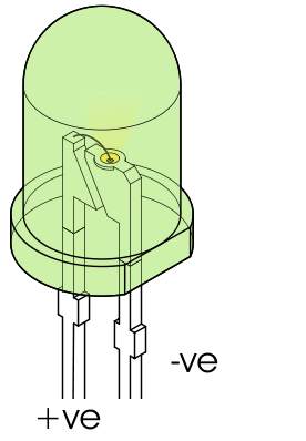
The final problem is which way round does the LED go? The usual answer is that if you look at the case of an LED it has a flat side. This marks the negative terminal i.e. the one that has to be connected to ground or zero volts.
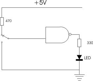
Almost done but we now need to work out how to connect the switches. Each switch has to connect the input of the gate to either +5V or to 0V and this is just a matter of a two position or two way switch. Simple and again it would work for a while. The problem is once again limiting the current. We need to put a resistor into the connection to the +5V to limit the current and again the calculation is simple as long as you know the characteristics of the gate. In practice lots of other people have worked this out before so you simply look at another circuit and see that has been used. In this case we need a 470 ohm resistor as shown:
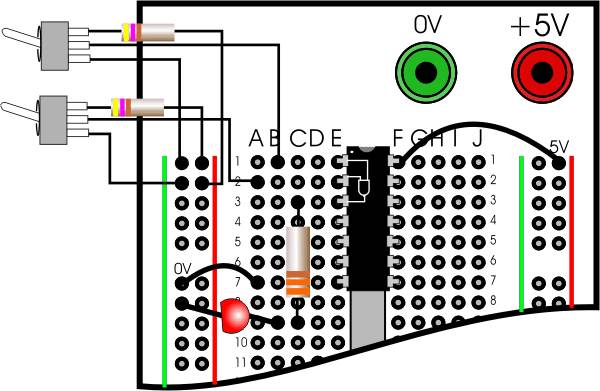
You can see now that with the switch in the up position the input is connected to +5V and with it in the down position the input is connected to 0V. Of course you also need a switch for the other input but this is identical. It is also worth saying that there is an easier way to wire up the input switch but for the moment lets stay with the direct approach. So how does this translate to the prototype board? Assuming that you have a +5V power supply and the components - 2 resistors, one 7400 and one Red LED it is fairly easy. You also need to know that resistors are identified by a color code - the first three colors give the value. You can look this up on Wikipedia but a 330 ohm resistor is Orange, Orange, Brown and a 470 is Yellow, Violet, Brown. The finished circuit can be seen below. Notice that the LED is has to be the correct way round and the 7400 has to be connected to power - pin 17 at +5V and ground pin 7 at 0V.
Click to enlarge
If you do make this circuit, then you will find that the LED goes on and off according to the switch positions, just as in the simulator. I hope now you believe me when I say that the simulator is so much simpler than real hardware! If you get the wiring wrong and, say, short an output to ground or apply the wrong power voltage then things will get hot. It's not dangerous, just costly and embarrassing. Even though it is harder, I hope you give it a try because we have lots of other interesting circuits to try out - but mainly using the simulator.
Getting Started With Digital Logic
<ASIN:B0DSSVDV76> <ASIN:187196279X> <ASIN:1871962803> <ASIN:1871962811> <ASIN:B0CK3X93KF>
More InformationRelated Articles
To be informed about new articles on I Programmer, sign up for our weekly newsletter, subscribe to the RSS feed and follow us on Facebook or Linkedin. 
Comments
or email your comment to: comments@i-programmer.info
<ASIN:1871962919> <ASIN:187196282X> <ASIN:187196279X> <ASIN:1871962803> <ASIN:1871962811> <ASIN:B0CK3X93KF> |
||||||||
| Last Updated ( Saturday, 11 January 2025 ) |