| The Pico In MicroPython: Direct To The Hardware |
| Written by Harry Fairhead & Mike James | |||||||||||||||||||||||||||||||||
| Monday, 13 December 2021 | |||||||||||||||||||||||||||||||||
Page 2 of 2
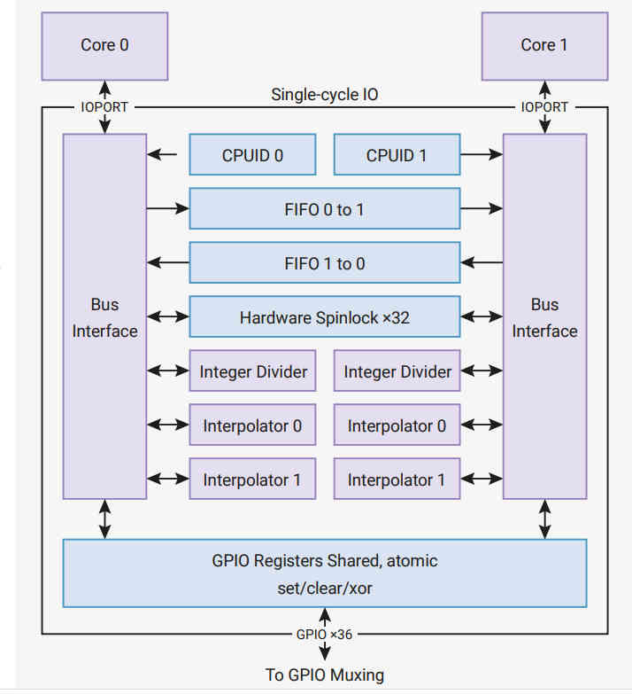
Single-Cycle IO BlockAt this point you might think that we are ready to access the state of the GPIO lines for general input and output. This isn’t quite the whole story. To accommodate the fact that the processor has two cores, and to make access faster to important devices, there is a special connection, the SIO or Single-cycle IO Block, between the cores and, among other things, the GPIO. The SIO connects directly to the two cores and they can perform single-cycle 32‑bit reads and writes to any register in the SIO. Notice that the SIO is not connected via the general address bus. You can see the general structure of the SIO in the diagram below. You can find out about the other devices it connects to from the documentation - our focus is on the GPIO lines. Notice that the GPIO lines are multipurpose and the SIO only has control when they are being used as GPIO lines. In this sense the SIO is just another peripheral that can take control of a GPIO line. The SIO provides a set of registers that makes using the GPIO much faster and much easier. The basic registers are: GPIO_OUT Sets all GPIO lines to high or low GPIO_IN Reads all GPIO lines GPIO_OE Sets any GPIO line to output driver or high impedance There are also three registers – SET, CLR and XOR - that make working with GPIO_OUT and GPIO_OE easier. Each of these can be thought of as a mask that sets, clears or XORs bits in the corresponding register. For example, GPIO_OUT_SET can be used to set just those bits in GPIO_OUT that correspond to the positions that are set high. The locations of these registers are as offsets from 0xd0000000:
Blinky RevisitedNow we can re-write Blinky yet again, but this time using direct access to the SIO GPIO registers. from machine import mem32,Pin from time import sleep_ms led=Pin(25,mode=Pin.OUT) addrSIO = 0xd0000000 while True: mem32[addrSIO + 0x014] = 1 << 25 sleep_ms(500) mem32[addrSIO + 0x018] = 1 << 25 sleep_ms(500) This program uses the standard MicroPython class to set the GPIO line to SIO control and output. If you think that this is cheating, it is an exercise to set the line correctly using the GPIO control register and the SIO. This example is a demonstration rather than being useful, but there are some very useful functions we can write using our knowledge of how the GPIO lines are controlled. MicroPython is limited to controlling a single GPIO line at a time, but the hardware can change or read multiple GPIO lines in a single register operation. For example: def gpio_get():
return mem32[0xd0000000+0x010]
Here the get function simply reads the GPIO_OUT register which has a single bit for the output state of each GPIO line. Notice that GPIO lines set to output reflect their last written-to state. A set function simply writes the mask to the GPIO_OUT_SET register def gpio_set(mask):
mem32[0xd0000000+0x014] = mask
A clear function is just as easy and this just writes to the GPIO_OUT_CLR register: def gpio_clear(mask):
mem32[0xd0000000+0x18C] = mask
You can easily create functions for reset and other logical operations on all of the GPIO lines in one operation, but a single mask value function is usually sufficient: def gpio_set(value,mask):
mem32[0xd0000000+0x01C] =
This writes to the GPIO_OUT_XOR register, but it writes a combination of a mask and a value. The mask gives the GPIO lines that need to be changed and the value gives the state they are to be set to. For example, if mask is 0111 and value is 0100 then value & mask is 0100. If this is XORed with the current state of the lines – e.g. 0101, in this case the result is 0001, which changes the state of only GP0 to a zero. Thus we have set lines GP2, GP1 and GP0 as specified in the mask to the corresponding bits in the value, i.e. 0100. Notice that this process sets the lines selected in the mask to either a zero or a one as determined by the bits in value. As demonstrated in Chapter 4, the value,mask function can be used to set GPIO lines simultaneously: from machine import Pin import machine def gpio_get(): return machine.mem32[0xd0000000+0x010] def gpio_set(value,mask): machine.mem32[0xd0000000+0x01C]= This sets lines GP21 and GP22 to 01 and 10 on each pass through the loop:
In Chapter But Not In This Extract
Summary
Programming the Raspberry Pi Pico/W In MicroPython Third EditionBy Harry Fairhead & Mike James
Buy from Amazon. Contents
Also of interest: **** articles from the second edition not yet updated. <ASIN:B0BR8LWYMZ> <ASIN:B0BL1HS3QD> To be informed about new articles on I Programmer, sign up for our weekly newsletter, subscribe to the RSS feed and follow us on Facebook or Linkedin. 
Comments
or email your comment to: comments@i-programmer.info |
|||||||||||||||||||||||||||||||||
| Last Updated ( Tuesday, 06 August 2024 ) |