| The Pico In MicroPython: ADC |
| Written by Mike James & Harry Fairhead | ||||
| Monday, 13 March 2023 | ||||
Page 1 of 3 Analog to Digital Conversion, ADC, is basic to many measurements and it is suprisingly easy as long as you don't need high accuracy. If you do then you need an add-on ADC. This is an extract from our book all about the Raspberry Pi Pico in MicroPython. Programming the Raspberry Pi Pico/W In MicroPython Third EditionBy Harry Fairhead & Mike James
Buy from Amazon. Contents
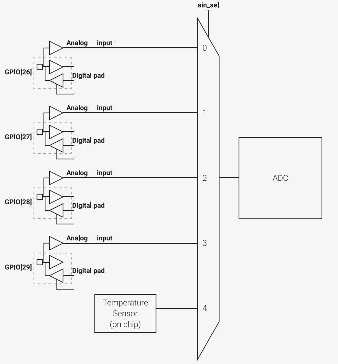
Also of interest: **** articles from the second edition not yet updated. <ASIN:B0BR8LWYMZ> <ASIN:B0BL1HS3QD> The SPI bus can be difficult to make work at first, but once you know what to look for about how the slave claims to work it gets easier. To demonstrate how it is done, let's add eight channels of 12-bit A‑to‑D using the MCP3008. The Pico has a single A‑to‑D Converter (ADC) with analog inputs, four of which can be used via external pins. Before moving on to look at the use of SPI to add more A‑to‑D converters, let’s take a look at those the Pico already has. If you are only interested in the detail of using the SPI bus, skip to that section. Pico ADCThe Pico has a single onboard ADC which has four multiplexed inputs. Three are available on the external pins and one is used for an internal temperature sensor.
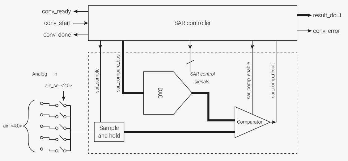
You can see from the diagram that pins GP26, GP27, GP28 and GP29 can be used as analog inputs. The ADC is a successive approximation converter. You don't need to know how it works to use it, but it isn't difficult to understand. The input voltage is compared to a standard voltage, VREF. The idea is that first a voltage equal to VREF/2 is generated and the input voltage is compared to this. If it is lower then the most significant bit is a 0 and if it is equal or greater then it is a 1. At the next step the voltage generated is VREF/2+VREF/4 and the comparison is repeated to generate the next bit. Successive approximation converters are easy to build, but they are slow. The Pico’s ADC needs 96 clock cycles to create a 12-bit result, which gives a maximum sampling rate of 500kS/s with a default clock of 48MHz.
AccuracyThe Pico’s ADC is very useful, but it isn’t as accurate as you might hope. Although it has 12 bits, the claimed effective accuracy is only 9 bits and most of this loss of precision is due to the way the reference voltage is supplied and to noise due to its integration with other digital devices. According to the documentation, you can improve the accuracy by modifying the reference voltage: For much improved ADC performance, an external 3.0V shunt reference, such as LM4040, can be connected from the ADC_VREF pin to ground. Note that if doing this the ADC range is limited to 0-3.0V signals (rather than 0-3.3V), and the shunt reference will draw continuous current through the 200R filter resistor (3.3V-3.0V)/200 = ~1.5mA. The ADC can be set to do conversions continuously, reading each of the possible inputs in a round-robin fashion, storing the results in an 8-deep FIFO (the documentation says 4-deep) buffer. Alternatively, you can simply start a conversion on a given input when you need the data – this is the only mode that MicroPython supports. The simplest way of using the ADC is to perform a single read of a single input under software control. Before making use of it, you have to create an ADC object associated with the channel: adc=machine.ADC(channel) Once you have selected the input you are going to read, you can start a conversion and get the result using: The result is in the range 0-65535 and this has to be scaled to give a physically meaningful reading. The simplest A‑to‑D program you can write is: import machine
import utime
sensor_temp = machine.ADC(4)
conversion_factor = 3.3 / (65535)
while True:
reading = sensor_temp.read_u16() * conversion_factor
temperature = 27 - (reading - 0.706)/0.001721
print(temperature)
utime.sleep(2)
This reads the temperature sensor which has a temperature voltage relationship given by: T = 27 – (V - 0.796)/0.001721 You can create individual ADC objects for each channel and read them in nay order. If you want to use any of the more advanced features of the Pico’s ADC you will need to either create the functions that directly access the hardware or move to C. |
||||
| Last Updated ( Wednesday, 15 March 2023 ) |