| The Pico In MicroPython: ADC |
| Written by Mike James & Harry Fairhead | |||||||
| Monday, 13 March 2023 | |||||||
Page 3 of 3
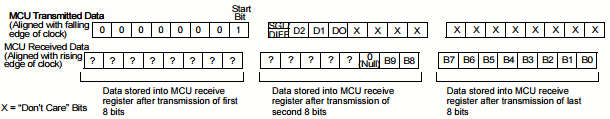
Basic ConfigurationNow we come to the configuration of the SPI bus. We have some rough figures for the SPI clock speed - around 10kHz to a little more than 1.35MHz. So a clock frequency of 500kHz seems a reasonable starting point. From the datasheet, the chip select has to be active low and, by default, data is sent most significant bit first for both the master and the slave. The only puzzle is what mode to use? This is listed in the datasheet as mode 0 0 with clock active high or mode 1 1 with clock active low. For simplicity we will use mode 0 0. We now have enough information to initialize the slave: spi = SPI(0, sck=Pin(18), miso=Pin(16), mosi=Pin(19)) spi.init(baudrate=500_000, bits=8, polarity=0, The ProtocolNow we have the SPI initialized and ready to transfer data, but what data do we transfer? As already discussed in the previous chapter, the SPI bus doesn't have any standard commands or addressing structure. Each device responds to data sent in different ways and sends data back in different ways. You simply have to read the datasheet to find out what the commands and responses are. Reading the datasheet might be initially confusing because it says that you have to send five bits to the slave - a start bit, a bit that selects its operating mode single or differential, and a 3-bit channel number. The operating mode is 1 for single-ended and 0 for differential. So to read Channel 3, i.e. 011, in single-ended mode you would send the slave:
where an That is, the slave sends back:
where The remaining nine bits are sent back in response to the next nine clock pulses. This means you have to transfer three bytes to get all ten bits of data. This all makes reading the data in 8-bit chunks confusing. The datasheet suggests a different way of doing the job that delivers the data more neatly packed into three bytes. What it suggests to send a single byte is:
At the same time, the slave transfers random data, which is ignored. The final 1 is treated as the start bit. If you now transfer a second byte with most significant bit indicating single or differential mode, then a 3-bit channel address and the remaining bits set to 0, the slave will respond with the null and the top two bits of the conversion. Now all you have to do to get the final eight bits of data is to read a third byte:
Using this information we can now write some instructions that read a given channel. For example, to read Channel 0 we first send a byte set to CS.low() write=bytearray([0x01, 0x80, 0x00]) read=bytearray(3) spi.write_readinto(write,read) CS.high() Notice you cannot send the three bytes one at a time using transfer because that results in the CS line being deactivated between the transfer of each byte. To get the data out of rBuff we need to do some bit manipulation: data = (read[1] & 0x03) << 8 | read[2] The first part of the expression extracts the low three bits from the first byte the slave sent and, as these are the most significant bits, they are shifted up eight places. The rest of the bits are then ORed with them to give the full 10‑bit result. To convert to volts we use: volts = data * 3.3 / 1023.0 assuming that VREF is 3.3V. In a real application you would also need to convert the voltage to some other quantity, like temperature or light level. If you connect a logic analyzer to the SPI bus you will see something like:
The complete program is: from utime import sleep_ms from machine import Pin, SPI from time import sleep spi = SPI(0, sck=Pin(18), miso=Pin(16), mosi=Pin(19)) spi.init(baudrate=500_000, bits=8, polarity=0, In chapter but not in this extract
Summary
Programming the Raspberry Pi Pico/W In MicroPython Third EditionBy Harry Fairhead & Mike James
Buy from Amazon. Contents
Also of interest: **** articles from the second edition not yet updated. <ASIN:B0BR8LWYMZ> <ASIN:B0BL1HS3QD> To be informed about new articles on I Programmer, sign up for our weekly newsletter, subscribe to the RSS feed and follow us on Facebook or Linkedin. 
Comments
or email your comment to: comments@i-programmer.info |
|||||||
| Last Updated ( Wednesday, 15 March 2023 ) |