| Exploring Edison - I2C Measuring Temperature And Humidity |
| Written by Harry Fairhead | ||||||||||||||||||||||||||||||||||||||
| Monday, 07 December 2015 | ||||||||||||||||||||||||||||||||||||||
Page 1 of 3 Using I2C devices is fairly easy once you have successfully used one - and hence know what information you need and what to look for in a working system. In this chapter we use the HTU21D temperature and humidity sensor as a case study of I2C in action. It also happens to be a useful sensor. This is a chapter from our ebook on the Intel Edison. The full contents can be seen below. Notice this is a first draft and a work in progress. Use the comments or email harry.fairhead@i-programmer.info with your queries or suggestions.
Now On Sale!You can now buy a print edition of Exploring Intel Edison.You can buy it from:
USA and World Amazon.com Chapter List
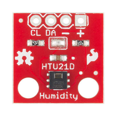
<ASIN:1871962447> Using an I2C device has two problems - the physical connection between master and slave and second figuring out what the software has to do to make it work. In this chapter we take the principle outlined in the previous one , see Exploring Edison - I2C Bus, and add the information in the HTU21D data sheet to make a working temperature humidity sensor using mraa. There is a C++ implementation of the HTU21D in the upm library and you can use this if it is more appropriate to your project. In this case it is the details of the implementation that is important. First the hardware. The SparkFun HTU21DThe HTU21D Humidity and Temperature sensor is one of the easiest of I2C devices to use with the Edison mini breakout board. The reason is that it works at 1.5V and therefore works with the Edison's 1.8V logic and use its power supply. This means you don't have to worry about level shifting and this simplifies your first encounter with I2C and provides an attractive way to measure temperature and humidity in a very small package. The only problem is that the HTU21D is only available in a surface mount package. To overcome this simply solder some wires onto the pads, it is possible to do, or you can buy a general breakout board. However, it is much simpler to buy the SparkFun HTU21D breakout board because this has easy connections and built-in pull up resistors. This means that you don't need to add any components to get this circuit working - just four connections.
https://www.sparkfun.com/products/12064 Don't worry about the fact that board and the documentation suggests that this only works at 3.3V - it works "best" at 3.3V, but it also works at 1.8V. If you use the HTU21D breakout then for prototyping the only thing you have to do is solder some pins or wires to the pads. If you decide to work with some other I2C device you can still follow the steps in this account, but you would have to modify what you do to be correct for the device you are using. In particular if you select a device that works at 3.3V or 5V you need a level convertor and you might also need pull-up resistors.
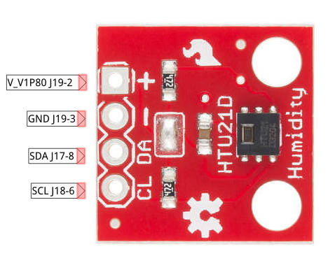
Wiring the HTU21DAs we are going to use a 1.8V sensor and I2C bus 1 the pins that we are going to use are:
Given that the HTU21D has pull up resistors and works at 1.8V connecting it to I2C 1 on the Edision is trivial:
You can use a prototype board to make the connections and this makes it easier to connect other instruments such as a logic analyser. A First ProgramAfter wiring up any i2C device the first question that needs to be answered is - does it work? Unfortunately for most complex devices finding out if it works is a multi-step process. Our first program will aim to read some data back from the HTU21D - any data will do. If you look at the data sheet you will find that the device address is 0x40 and its supports the following commands:
The easiest of these to get started with is the Read user register command. The user register gives the current setup of the device and can be used to set the resolution of the measurement. Notice that the codes that you send to the device can often be considered addresses or commands. In this case you can think of sending 0xE7 as a command to read the register or the read address of the register - it makes no difference. In most cases the term command is used when sending the code makes the device do something and and the term address is used when it simply makes the device read or write specific data. To read the user register we have to write a byte containing 0xE7 and then read the byte the device sends back. Notice that means sending an address frame, a data frame and then another address frame and reading a data frame. You can do this in two ways. The first is to use raw byte read and write commands:
This program sets up I2C-1, sets the address to 0x40 and then sends 0xE7 and immediately reads a byte that the device sends back. If you run this program you will see: Register= 66 this is the default value of the register and it corresponds to a resolution of 12 and 14 bits for the humidity and temperature respectively. <ASIN:B00O9PMEHY@UK> <ASIN:B00ND1KH42@COM> <ASIN:B00ND1KNXM> <ASIN:B00ND1KH10> |
||||||||||||||||||||||||||||||||||||||
| Last Updated ( Saturday, 27 February 2016 ) |