| Exploring Edison - SPI |
| Written by Harry Fairhead | ||||||||||||||||||||||||||||||||||||||||||||||||||||||||||||||||||||||||
| Thursday, 02 June 2016 | ||||||||||||||||||||||||||||||||||||||||||||||||||||||||||||||||||||||||
Page 1 of 5 The SPI bus can be something of a problem because it doesn't have a well defined standard that every device conforms to. Even so, if you only want to work with one specific device it is usually easy to find a configuration that works - as long as you understand what the possibilities are. This is a chapter from our ebook on the Intel Edison. The full contents can be seen below. Notice this is a first draft and a work in progress. Use the comments or email harry.fairhead@i-programmer.info with your queries or suggestions.
Now On Sale!You can now buy a print edition of Exploring Intel Edison.You can buy it from:
USA and World Amazon.com Chapter List
<ASIN:1871962447> SPI Bus BasicsThe SPI bus is commonly encountered as it is used to connect all sorts of devices from LCD displays, through real time clocks, to AtoD converters. It is also used for high data rate streaming, for example, getting video data from a camera. The SPI bus is strange because there is no standards for it and different companies have implemented it in different ways which means that you have to work harder to implement it in any particular case. However, it does usually work, which is a surprise for a bus with no standard or clear specification. The reason it can be made to work is that you can specify a range of different operating modes, frequencies and polarities. This makes the bus slightly more complicated to use, but generally it is a matter of looking up how the device you are trying to work with implements the SPI bus and then getting the Edison to work in the same way. The bus is odd in another way - it does not use bidirectional serial connections. There is a data line for the data to go from the master to the slave and a separate data line from the slave back to the master. That is, instead of a single data line that changes its transfer direction, there is one for data out and one for data in. There is a variation on the SPI bus that does use a bidirectional mode where a single wire is used for the data, but the Edison doesn't support this. It is also worth knowing that the drive on the SPI bus is push-pull and not open collector/drain. This provides higher speed and more noise protection as the bus is driven in both directions. You can see the sort of configuration that the Edison expects. There is a single master and at most two slaves. The signal lines are:
There can also be any number of SS - Slave Select - or CE Chip Select - lines which are usually set low to select which slave is being addressed. Notice that unlike other buses I2C for example there are no SPI commands or addresses - only bytes of data. However slave devices do interpret some of the data as commands to do something or send some particular data. The Edison has only a single SPI bus exposed on the mini breakout board and only two SS lines. This means that in principle you can only connect two SPI devices. In practice mraa only uses CS1 and so you can only connect a single slave device. This can be overcome by using GPIO lines as chip select lines and/or using CS0 directly.
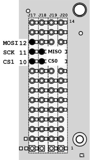
The pins that are used for the Edison's SPI bus are:
The data transfer on the SPI bus is also slightly odd. What happens is that the master pulls one of the chip selects low which activates a slave. Then the master toggles the clock SCLK and both the master and the slave send a single bit on their respective data lines. After eight clock pulses a byte has been transferred from the master to the slave and from the slave to the master. You can think of this as being implemented as a circular buffer - although it doesn't have to be.
This full duplex data transfer is often hidden by the software and the protocol used. For example there is a read function that reads data from the slave and sends zeros or data that is ignored by the slave. Similarly there is a write function that sends valid data but ignores whatever the slave sends. The transfer is typically in groups of eight bits and usually most significant bit first but this isn't always the case. In general as long as the master supply clock pulses data is transferred. Notice this circular buffer arrangement allows for slaves to be daisy chained with the output of one going to the input of the next. This makes the entire chain one big circular shift register. This can make it possible to have multiple devices with only a single chip select but it also means any commands sent to the slaves are received by each one in turn. For example you could send a convert command to each AtoD converter in turn and receive back results from each one. (See:https://www.maximintegrated.com/en/app-notes/index.mvp/id/3947) The final odd thing about the SPI bus is that there are four modes which define the relationship between the data timing and the clock pulse. The clock can be either active high or low - clock polarity CPOL and data can be sampled on the rising or falling edge of the clock - clock phase CPHA. All combinations of these two possibilities gives the four modes:
The way that the modes are named is common but not universal. There is often a problem trying to work out what mode a slave device uses. The clock polarity is usually easy and the Clock phase can sometimes be worked out from the data transfer timing diagrams and:
So, to configure the SPI bus to work with a particular slave device you have to
Now we have to find out how to do this using the mraa library. |
||||||||||||||||||||||||||||||||||||||||||||||||||||||||||||||||||||||||
| Last Updated ( Thursday, 02 June 2016 ) |