| Exploring Edison - The DS18B20 1-Wire Temperature Sensor |
| Written by Harry Fairhead | |||||
| Monday, 07 March 2016 | |||||
Page 1 of 4 The Edison doesn't have built in support for the Maxim 1-Wire bus and this means you can't use the very popular DS18B20 temperature sensor. However with a little careful planning you can and you can do it from user rather than kernel space. This is a chapter from our ebook on the Intel Edison. The full contents can be seen below. Notice this is a first draft and a work in progress. Use the comments or email harry.fairhead@i-programmer.info with your queries or suggestions.
Now On Sale!You can now buy a print edition of Exploring Intel Edison.You can buy it from:
USA and World Amazon.com Chapter List
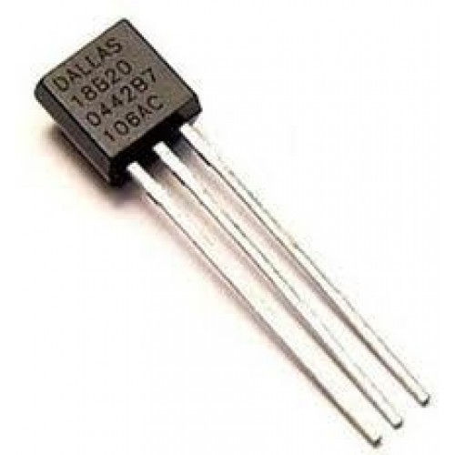
<ASIN:1871962447> The Maxim 1-Wire bus is a proprietary bus that is very easy to use and has a lot of useful devices you can connect to it including their iButton security devices. However probably the most popular of all 1-wire devices is the DS18B20 temperature sensor - it is small, very cheap and very easy to use. Easy to use - but only if the processor supports the 1-wire bus protocol and the Edison doesn't. However the protocol is easy enough to program in C and the Edison is fast enough to work with it without needing anything extra other than memory mapped I/O. The HardwareThe DS18B20 is available in an number of formats but the most common makes it look just like a standard BJT - which can sometimes be a problem when you are trying to find one.
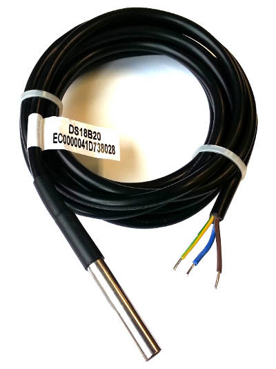
You can also get them made up into waterproof sensors complete with cable.
No matter how packaged they will work at 3.3V or 5V but not at 1.8V without a level converter. Its basic specification is:
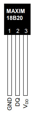
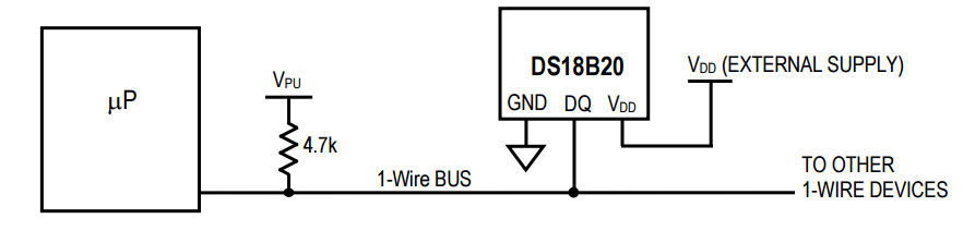
It can also be powered from the data line making the bus physically need only two wires - data and ground - however this "parasitic power" mode is difficult to make work reliably and best avoided in an initial design. In normal powered mode there are just three connections:
Ground needs to be connected to the system ground, VDD to 3.3V and DQ to the pullup resistor of an open collector bus.
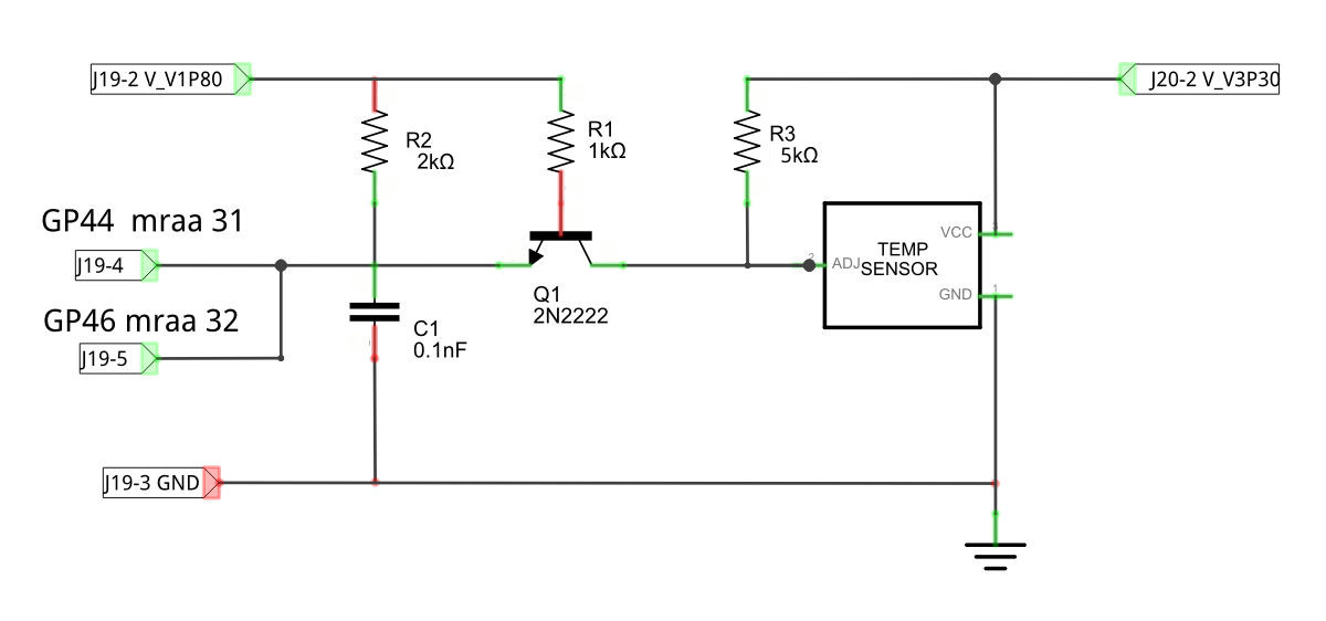
There can be multiple devices on the bus and each one has a unique 64bit lasered ROM code which can be used as an address to select the active devices. For simplicity it is better to start off with a single device and avoid the problem of enumerating the devices on the bus - although once you know how everything works this isn't difficult to implement. As we only have a single bus master, the Edison and a single slave device, the DS18B20, we can use the same single transistor level shift introduced in earlier chapters. However there is an additional problem we have to solve - fast switching between input and output. In the previous chapter we were able to implement the serial protocol because essentially the Edison sent the device a pulse and then the device did all the talking. This allowed the use of a single GPIO line. It first was set to output, used to send a pulse then switched to input mode ready to read the 40 bits of data. The problem is that changing between output and input mode is done using the SYSFS drivers and it is comparatively slow - 15 to 20 microseconds. Fortunately in the example of the DHT22 because it simply resulting in missing part of the acknowledge pulse. The Edison was ready to read data well before the device started to send it. In the case of the 1-wire bus things are very different. The master has to send a fast pulse on the line for every bit received and it has to be able to read the response in 15 microseconds. This is too fast to allow for time to change the line from output to input in time to read the data. However given the specification of the 1-wire bus it might be possible most of the time and with some devices. A more secure solution that should work with all 1-wire bus devices is to use two GPIO lines - one set to output and one set to input. This works because it eliminates the need to change the line's direction but it does mean that you need to use two GPIO lines to drive the 1-wire bus. As long as you can afford this doubling up of GPIO lines then the solution works well. The schematic of the level shifter and the DS18B20 is:
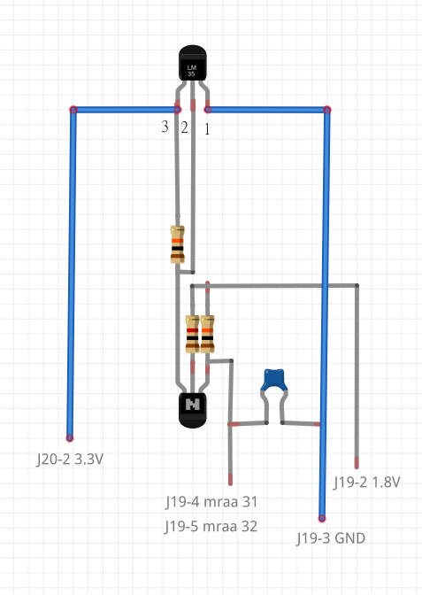
You will notice that it is the same circuit used in the previous chapter with the DS18B20 replacing the DHT22 and a second GPIO line connected. The pullup resistor R2 can be supplied by the Edison and if you opt to use its internal pullup you can omit R2 from the hardware. In the rest of the chapter is it assumed that R2 is present in the sensor and not supplied by the Edison. When you are first trying things out it is worth using a prototype board but this level shifter can be assembled in place on the DS18B20 to effectively convert the sensor to 1.8V operation:
Again use heat shrink sleeving to avoid shorts between component wires. The disadvantage is that now we need four wires back to the Edison whereas only three are needed for a 3.3V device. <ASIN:B00O9PMEHY@UK> <ASIN:B00ND1KH42@COM> <ASIN:B00ND1KNXM> <ASIN:B00ND1KH10> |
|||||
| Last Updated ( Wednesday, 11 May 2016 ) |