| The Pico In MicroPython: Simple Input |
| Written by Harry Fairhead & Mike James | ||||||
| Monday, 17 January 2022 | ||||||
Page 2 of 2
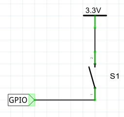
If you change PULL_UP to PULL_DOWN, the way the switch is connected becomes:
The program still works, but now GP22 is high when the switch is pressed and hence the LED is on when the switch is pressed. Should you use an internal or external resistor? The answer is that it mostly doesn’t matter as long as there is a resistor. The only problem with using an internal resistor is the possibility that the software fails to set the pull-up/down mode and leaves the input floating. Also notice that this switch input is not debounced. The simplest way to do this is include a time delay in the loop before the line is sampled again. If you want to respond to a button press, that is a press and a release event, then you have to test for a double transition: from machine import Pin
import time
pinIn = Pin(22, Pin.IN,Pin.PULL_DOWN)
pinLED = Pin(25, Pin.OUT)
while True:
while pinIn.value()==0:
pass
while pinIn.value()==1:
pass
pinLED.on()
time.sleep(1)
pinLED.off()
In this case you really do need the debounce delays if you want to avoid responding twice to what the user perceives as a single press. A 1‑millisecond delay is probably the smallest delay that produces a button that feels as if it works. In practice, you would have to tune the delay to suit the button mechanism in use and the number of times you can allow the button to be pressed in one second. Press Or HoldYou can carry on elaborating on how to respond to a button. For example, most users have grown accustomed to the idea that holding a button down for a longer time than a press makes something different happen. To distinguish between a press and a hold all you need to do is time the difference between line down and line up: from machine import Pin
import time
pinIn = Pin(22, Pin.IN,Pin.PULL_DOWN)
pinLED = Pin(25, Pin.OUT)
while True:
while pinIn.value()==0:
pass
t=time.ticks_ms()
time.sleep_ms(1)
while pinIn.value()==1:
pass
t=time.ticks_diff(time.ticks_ms(),t)
if t<2000:
pinLED.on()
time.sleep(1)
pinLED.off()
else:
for i in range(10):
pinLED.on()
time.sleep_ms(100)
pinLED.off()
time.sleep_ms(100)
In this case holding the button for 2s registers a “held” – the LED flashes 10 times and anything less is a “push” – the LED flashes just once. Notice the 1ms debounce pause between the test for no-press and press. One of the problems with all of these sample programs is that they wait for the button to be pressed or held and this makes it difficult for them to do anything else. You have to include whatever else your program needs to do within the loop that waits for the button – the polling loop. You can do this in an ad hoc way, but the best approach is to implement a finite state machine, see later. How Fast Can We Measure?Buttons are one form of input, but often we want to read data from a GPIO line driven by an electronic device and decode the data. This usually means measuring the width of the pulses and this raises the question of how fast can we accept input? The simplest way to find out how quickly we can take a measurement is to perform a pulse width measurement. Applying a square wave to GP22 we can measure the time that the pulse is high using: from machine import Pin
import time
pinIn = Pin(22, Pin.IN)
while True:
while pinIn.value()==1:
pass
while pinIn.value()==0:
pass
t=time.ticks_us()
while pinIn.value()==1:
pass
t=time.ticks_diff(time.ticks_us(),t)
print(t)
time.sleep(1)
This might look a little strange at first. The inner while loops are responsible for getting us to the right point in the waveform. First we loop until the line goes low, then we loop until it goes high again and finally measure how long before it goes low. You might think that we simply have to wait for it to go high and then measure how long till it goes low, but this misses the possibility that the signal might be part way through a high period when we first measure it. This can be measured down to around 30µs with a very poor accuracy at this limit and an accuracy of 5 to 10µs for longer times . Notice that in either case if you try measuring pulse widths much shorter than the lower limit that works, you will get results that look like longer pulses are being applied. The reason is simply that the Pico will miss the first transition to zero but will detect a second or third or later transition. This is the digital equivalent of the aliasing effect found in the Fourier Transform or general signal processing.
MicroPython also provides a special method that implements the algorithm used in the above program. The method: machine.time_pulse_us(pin, level, timeout) will block until the pin specified changes to the level specified or the timeout occurs. Once the pin attains the level specified it times how long it takes for it to change and returns the result in microseconds. The only problem is that, if the pin is already at the specified level, the timing begins at once. Using this method the program above can be written more simply as: import time
import machine
pinIn = machine.Pin(22, machine.Pin.IN)
while True:
t = machine.time_pulse_us(pinIn, 1)
print(t)
time.sleep(1)
Notice that you will get some fractional measurements using this method. To get accurate results you would have to be sure that the line was at zero just before the method is used. For example: import machine
import time
import machine
pinIn = machine.Pin(22, machine.Pin.IN)
while True:
while pinIn.value() == 1:
pass
t = machine.time_pulse_us(pinIn, 1)
print(t)
time.sleep(1)
The time_pulse_us method is not a big improvement on the more basic way of doing the job, but it is more accurate for lengthier intervals. In chapter but not in this extract
Summary
Programming the Raspberry Pi Pico/W In MicroPython Third EditionBy Harry Fairhead & Mike James
Buy from Amazon. Contents
Also of interest: **** articles from the second edition not yet updated. <ASIN:B0BR8LWYMZ> <ASIN:B0BL1HS3QD>
To be informed about new articles on I Programmer, sign up for our weekly newsletter, subscribe to the RSS feed and follow us on Facebook or Linkedin. 
Comments
or email your comment to: comments@i-programmer.info
|
||||||
| Last Updated ( Friday, 18 March 2022 ) |