| Raspberry Pi IoT In C - 1‑Wire Bus Basics |
| Written by Harry Fairhead | ||||||
| Monday, 03 October 2022 | ||||||
Page 2 of 2
Writing BitsOur next task is to implement the sending of some data bits to the device. The 1‑wire bus has a very simple data protocol. All bits are sent using a minimum of 60µs for a read/write slot. Each slot must be separated from the next by a minimum of 1µs. The good news is that timing is only critical within each slot. You can send the first bit in a time slot and then take your time before you send the next bit as the device will wait for you. This means you only have to worry about timing within the functions that read and write individual bits.
It seems reasonable to use the typical timings given in the datasheets. So for a 0 we hold the line low for 60µs then let it go high for the remainder of the slot, 10µs. To send a 1 we hold the line for 6µs and then let it go high for the remainder of the slot, 64µs. As the only time critical operations are the actual setting of the line low and then back to high, there is no need to worry too much about the speed of operation of the entire function so we might as well combine writing 0 and 1 into a single writeBit function: void writeBit(uint8_t pin, int b) {
int delay1, delay2;
if (b == 1) {
delay1 = 6;
delay2 = 64;
} else {
delay1 = 60;
delay2 = 10;
}
bcm2835_gpio_fsel(pin, BCM2835_GPIO_FSEL_OUTP);
bcm2835_gpio_write(pin, LOW);
bcm2835_delayMicroseconds(delay1);
bcm2835_gpio_fsel(pin, BCM2835_GPIO_FSEL_INPT);
bcm2835_delayMicroseconds(delay2);
}
The code at the start of the function simply increases the time between slots slightly. Notice that once again we return the GPIO line to input, i.e. high impedance, rather than driving the line high at the end of the transaction. This allows the line to be pulled high ready for any response from the slave. You can see two 1s followed by two 0s in the following logic analyzer trace:
A First Command - Writing BytesAfter discovering that there is at least one device connected to the bus, the master has to issue a ROM command. In many cases the ROM command used first will be the Search ROM command, which enumerates the 64-bit codes of all of the devices on the bus. After collecting all of these codes, the master can use Match ROM commands with a specific 64-bit code to select the device the master wants to talk to. While it is perfectly possible to implement the Search ROM procedure, it is simpler to work with the single device by using commands which ignore the 64-bit code and address all of the devices on the bus at the same time. Of course, this only works as long as there is only one device on the bus. If there is only one device then we can use the Skip ROM command 0xCC to tell all the devices on the bus to be active. We now need a function that can send a byte. As we have a writeBit function this is easy: void sendskip(uint8_t pin){
writeBit(pin 0);
writeBit(pin 0);
writeBit(pin 1);
writeBit(pin 1);
writeBit(pin 0);
writeBit(pin 0);
writeBit(pin 1);
writeBit(pin 1);
}
Notice that 0xCC is 1100 1100 in binary and the 1‑wire bus sends the least significant bit first. If you try this out you should find it works but the device doesn't respond because it is waiting for another command. Again, as the time between writing bits isn't critical we can take this first implementation of the function and write something more general if slightly slower. The writeByte function will write the low eight bits of an int to the device: void writeByte(uint8_t pin, int byte) {
int i;
for (i = 0; i < 8; i++) {
if (byte & 1) {
writeBit(pin, 1);
} else {
writeBit(pin, 0);
}
byte = byte >> 1;
}
}
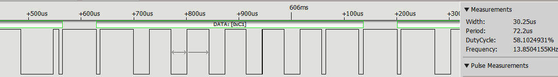
Using this we can send a Skip ROM command using: writeByte(RPI_BPLUS_GPIO_J8_07, 0xCC); You can see the pattern of bits sent on a logic analyzer:
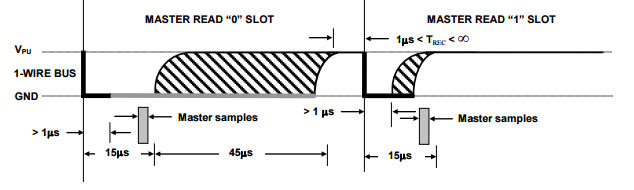
Reading BitsWe already know how the master sends a 1 and a 0. The protocol for the slave device is exactly the same except that the master still provides the slot’s starting pulse. That is, the master starts a 60µs slot by pulling the bus down for at least 1µs. Then the slave device either holds the line down for a further 15µs minimum or it simply allows the line to float high. See below for the exact timings:
So all we have to do to read bits is to pull the line down for more than 1µs and then sample the bus after pausing long enough for the line to be pulled up or held low. The datasheet gives 6µs for the master's pulse and a 9µs pause. In practice, a final delay of 2µs seems to work best and allows for the time to change the line's direction. uint8_t readBit(uint8_t pin) {
bcm2835_gpio_fsel(pin, BCM2835_GPIO_FSEL_OUTP);
bcm2835_gpio_write(pin, LOW);
bcm2835_delayMicroseconds(8);
bcm2835_gpio_fsel(pin, BCM2835_GPIO_FSEL_INPT);
bcm2835_delayMicroseconds(2);
uint8_t b = bcm2835_gpio_lev(pin);
bcm2835_delayMicroseconds(60);
return b;
}
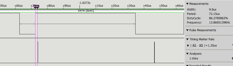
A logic analyzer shows the typical pattern of bits from the device:
By adding some commands to toggle a line after the sample is taken we can see how the timing works:
You might think that sampling so close to the rising edge of the timing pulse is a bad idea, but the timing of the sample tends to drift longer not shorter and this short timing reduces the error rate. Finally we need a function that will read a byte. As in the case of writing a byte, there is no time criticality in the time between reading bits so we don't need to take extra special care in constructing the function: int readByte(uint8_t pin) {
int byte = 0;
int i;
for (i = 0; i < 8; i++) {
byte = byte | readBit(pin) << i;
};
return byte;
}
The only difficult part is to remember that the 1‑wire bus sends the least significant bit first and so this has to be shifted into the result from the right. we can:
presence(uint8_t pin)
void writeByte(uint8_t pin, int byte)
int readByte(uint8_t pin) These functions will be used in the next two chapters to work with real 1‑wire devices. These are not the only functions we need to work with the 1‑wire bus. We need to be able to compute the CRC error checks that are commonly used to confirm that data has been transmitted correctly and we need to perform a ROM search to discover what devices are connected to the bus.
Summary
Raspberry Pi And The IoT In C Second EditionBy Harry Fairhead
Buy from Amazon. Contents
<ASIN:1871962633> <ASIN:B08KLNT2JC> To be informed about new articles on I Programmer, sign up for our weekly newsletter, subscribe to the RSS feed and follow us on Facebook or Linkedin. 
Comments
or email your comment to: comments@i-programmer.info |
||||||
| Last Updated ( Wednesday, 05 October 2022 ) |