| Raspberry Pi CM5 IoT In C - Getting Started With SPI |
| Written by Harry Fairhead | ||||||||
| Monday, 29 December 2025 | ||||||||
Page 4 of 4
Putting all of this together gives us the complete program: #include <stdio.h>
#include <stdlib.h>
#include <string.h>
#include <fcntl.h>
#include <unistd.h>
#include <sys/ioctl.h>
#include <linux/spi/spidev.h>
#include <stdint.h>
int main(int argc, char **argv)
{
checkSPI0();
uint8_t tx[] = {0xAA};
uint8_t rx[] = {0};
struct spi_ioc_transfer tr =
{
.tx_buf = (unsigned long)tx,
.rx_buf = (unsigned long)rx,
.len = 1,
.delay_usecs = 0,
.speed_hz = 500000,
.bits_per_word = 8,
};
int fd = open("/dev/spidev0.0", O_RDWR);
int status = ioctl(fd, SPI_IOC_MESSAGE(1), &tr);
if (status < 0)
printf("can't send data");
printf("%X,%X", tx[0],rx[0]);
close(fd);
}
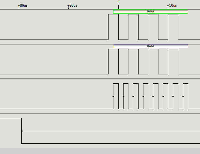
Note: The checkSPI0 function needs to be added to this listing. If you run the program and don't get any data, or receive the wrong data, then the most likely reason is that you have connected the wrong two pins, or not connected them at all. If you connect a logic analyzer to the four pins involved you will see the data transfer: If you look carefully you will see the CS0 line go low before the master places the first data bit on the MOSI, and hence on the MISO line. Notice that the clock rises in the middle of each data bit, making this a mode 0 transfer.
If you need to configure the SPI interface you can use the ioctl calls. For example: static uint8_t mode = 1;
int ret = ioctl(fd, SPI_IOC_WR_MODE, &mode);
if (ret == -1)
printf("can't set spi mode");
static uint8_t bits = 8;
ret = ioctl(fd, SPI_IOC_WR_BITS_PER_WORD, &bits);
if (ret == -1)
printf("can't set bits per word");
static uint32_t speed = 500000;
ret = ioctl(fd, SPI_IOC_WR_MAX_SPEED_HZ, &speed);
if (ret == -1)
printf("can't set max speed hz");
After this you should see mode 1 selected and the clock going high at the start of each bit. All of the SPI interfaces all have a set of drivers that follow a standard pattern, where n is the port number. They use one or two chips selects respectively:
If you don’t specify a pin to be used for the chip select then the default used is the pin shown above. SPI1 also has the possibility of using three chip selects:
It is also worth knowing that the drivers do not use the SPI hardware’s chip select implementation. Instead they use a general GPIO line and set it high and low under software control. This means you can use any GPIO line as a chip select, not just the ones supported by the hardware. You can also use the csm_spidev parameter to prevent the creation of an SPI driver node for the mth chip select. SPI0 is the same on all models of Pi and this is the one you should consider as first choice if you value compatibility. In Chapter but not included in this extract
Summary
Raspberry Pi Compute Module 5
|

Vite+ - A New Toolset 01/12/2025 There's a drop-in upgrade to Vite with additional features. The developers say Vite+ is a command-line developer tool you can install from npm, just like Vite itself. |
Codacy Releases AI Risk Reduction Tool 04/12/2025 Codacy has launched two new products to help control genAI coding. AI Risk Hub and AI Reviewer form a code compliance suite that organizations can use for governance of AI-generated code and sma [ ... ] |
More News
|

Comments
or email your comment to: comments@i-programmer.info