| Exploring Edison - Pulse Width Modulation |
| Written by Harry Fairhead | ||||
| Thursday, 29 October 2015 | ||||
Page 3 of 3
Changing the LED brightnessWhat about a linear change in brightness? To achieve this reasonably accurately isn't difficult all we need to do is increase the power or equivalently the duty cycle in steps that are cubic. If we just use 0 to 10 cubed we get a pulse width of 0 to 1000 which is ideal for our 1ms pulse used in the previous example i.e. 0 to 100% duty cycle. If we were working with a simple microcontroller then at this point we would need to consider using a lookup table for the steps as a way of increasing the performance. The Edison however has plenty of number crunching power so a direct implementation is possible:
As this produces 10 cubic steps a usleep of 40,000 makes each step last 4ms and so it takes 40ms to go from low to high. If you replace the delay with a value of 100,000 then you will get a 1 second cycle - which using only ten steps starts to look a little unsteady. You can increase the number of steps by simply dividing by a suitable factor. Dividing by 10 produces roughly 20 cubic step to get to 1000. At this point you would probably decide that a lookup table is essential, but again the Edison has no problem doing floating point arithmetic for this sort of problem:
Notice that now as there are twice as many steps we only need each one to last half the time, i.e. 50,000 microseconds. In most cases exactly how linear the response of the LED is is irrelevant. The only exception is when you are trying to drive LEDs to create a grey level or color display. Controlling a ServoHobby servos, the sort used in radio control models, are very cheap and easy to use and the Edison has enough PWM lines to control four of them without much in the way of extras. A basic servo has just three connections - usually ground and power line and a signal line. The colors used vary but the power is usually red and the ground line is usually black or brown. The signal line is white, yellow or orange.
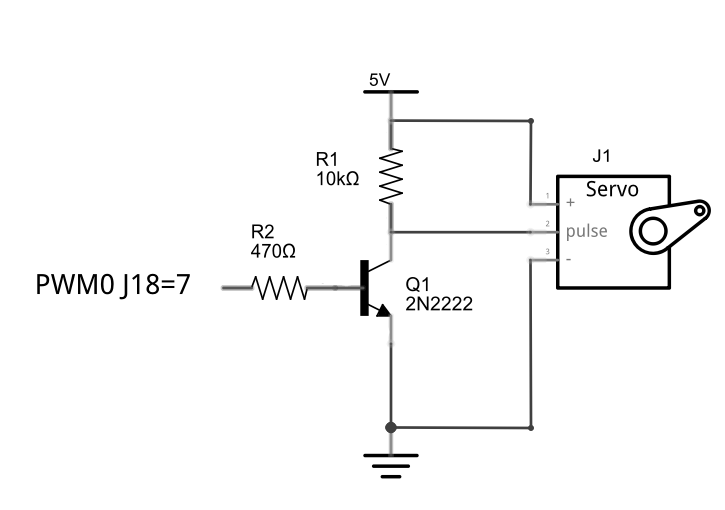
The power wire has to be connected to 5V supply capable of providing enough current to run the motor - anything up to 500mA or more depending on the servo. The good news is that the servo signal line generally needs very little current, although it does need to be switched between 0 and 5V using a PWM signal. You can assume that the signal line needs to be driven as a voltage load and so the appropriate way to drive the servo is:
The 10K resistor R1 can be a lot larger for most servos - 47K often works. Now all we have to do is set the PWM line to produce 20ms pulses with pulse widths ranging from 1 to 2 ms. If you implement this as a simple program you will discover that the servo does nothing at all - apart perhaps from vibrating. The reason is that the transistor voltage driver is an inverter. When the PWM line is high the transistor is fully on and the servo's pulse line is effectively grounded. When the PWM line is low the transistor is fully off and the servo's pulse line is pulled high by the resistor. A common solution to this problem is to drive the servo using an emitter follower configuration, but in this case this isn't possible because the maximum voltage an emitter follower configuration would generate is 1.8-0.6=1.2V, which is too low to drive most servos. The standard solution in this case is to use two transistors to generate a non-inverted pulse but it is possible to use a single transistor in a non-inverting configuration - see the chapter Life at 1.8V. The simplest solution of all is to ignore the problem in hardware and solve the problem in software. Instead of generating 20ms pulses with pulse widths 1 to 2ms, you can generate an inverted pulse with 20ms pulses with widths in the range 18 to 19 ms. The following program moves the servo between its two extreme positions and back again:
If you run this program you should find that the servo moves as promised - however it might not reach its limits of movement. Servos differ in how they respond to the input signal and you might need to calibrate the pulse widths. Many robot implementations, for example, calibrate the servos to find their maximum movement using either mechanical switches to detect when the servo is at the end of its range or a vision sensor. You can see from the logic analyser plot that the PWM pulse train is "inverted" as desired.
You can also see that the values used for the period and for the pulse width could do with some adjustment to bring them closer to the target values. In practice, however, servo calibration is the better answer. Given that the Edison has four PWM lines you can drive four servos without any additional hardware. Beyond four servos and you most likely need to use one of the many servo boards that are available. For example, SparkFun has an eight-line PWM board that is driven by the Edison's I2C bus - which is the subject of the next chapter. What Else Can You Use PWM For?PWM lines are incredibly versatile and it is always worth asking the question "could I use PWM?" when you are considering almost any problem. The LED example shows how you can use PWM as s power controller. You can extend this idea to a computer controlled switch mode power supply. All you need is a capacitor to smooth out the voltage and perhaps a transformer to change the voltage. The same idea can be used as a crude D to A converter. Change the LED for an 8 ohm loudspeaker and you have a way of generating sound. At its simplest you can feed the PWM signal into the speaker unmodified and create "space" sounds. However you can also add a filter and work at a higher pulse rate to create higher quality audio - and all without a USB dongle in sight. You can also use PWM to control the speed of a DC motor and if you add a simple bridge circuit you can control its direction and speed. Finally, you can use a PWM signal as a modulated carrier for data communications. For example, most infrared controller make use of a 38KHz carrier, which is roughly a 26 microseconds. This is switched on and off for 1ms and this is well within the range that the Edison PWM can manage. So all you have to do is replace the red LED in the previous circuit with an infrared LED and you have the start of a remote control or data transmission link.
More InformationThe starting point for finding out about all Intel's Internet of Things resources, including Edison, is the Intel IoT Developer Zone. Exploring Edison
Now On Sale!You can now buy a print edition of Exploring Intel Edison.You can buy it from:
USA and World Amazon.com Chapter List
<ASIN:1871962447> More InformationRelated ArticlesPowerful New Features For Edison To be informed about new articles on I Programmer, install the I Programmer Toolbar, subscribe to the RSS feed, follow us on, Twitter, Facebook, Google+ or Linkedin, or sign up for our weekly newsletter.
Comments
or email your comment to: comments@i-programmer.info
<ASIN:B00ND1KH42@COM>; <ASIN:B00ND1KNXM> <ASIN:B00ND1KH10>
|
||||
| Last Updated ( Friday, 06 May 2016 ) |